
Ventilation system

a technology of ventilation system and air intake, which is applied in the direction of transportation and packaging, vehicle heating/cooling devices, air-conditioning devices, etc., can solve the problem of system which consumes less power, and achieve the effect of increasing conduction, increasing contact area, and even further thermal efficiency

Inactive Publication Date: 2018-08-30
JAGUAR LAND ROVER LTD
View PDF5 Cites 1 Cited by
  • Summary
  • Abstract
  • Description
  • Claims
  • Application Information

AI Technical Summary

Benefits of technology

This patent describes a system for controlling the air conditioning and heating in a vehicle. The system has separate ducts for cold and hot air, which allows any heat or cold from the air outside the vehicle to be conducted into the air inside the vehicle. This results in a more efficient system as the air conditioning and heating systems don't have to work at such high levels. The system also takes into account the pollution in the outside air, and controls the air flow to keep the environment inside the vehicle clean.

Problems solved by technology

In addition, selectively operating the air propulsion element only when an air flow is required results in a system which consumes less power.

Method used


Image

  • Ventilation system
  • Ventilation system
  • Ventilation system

Examples


Embodiment Construction

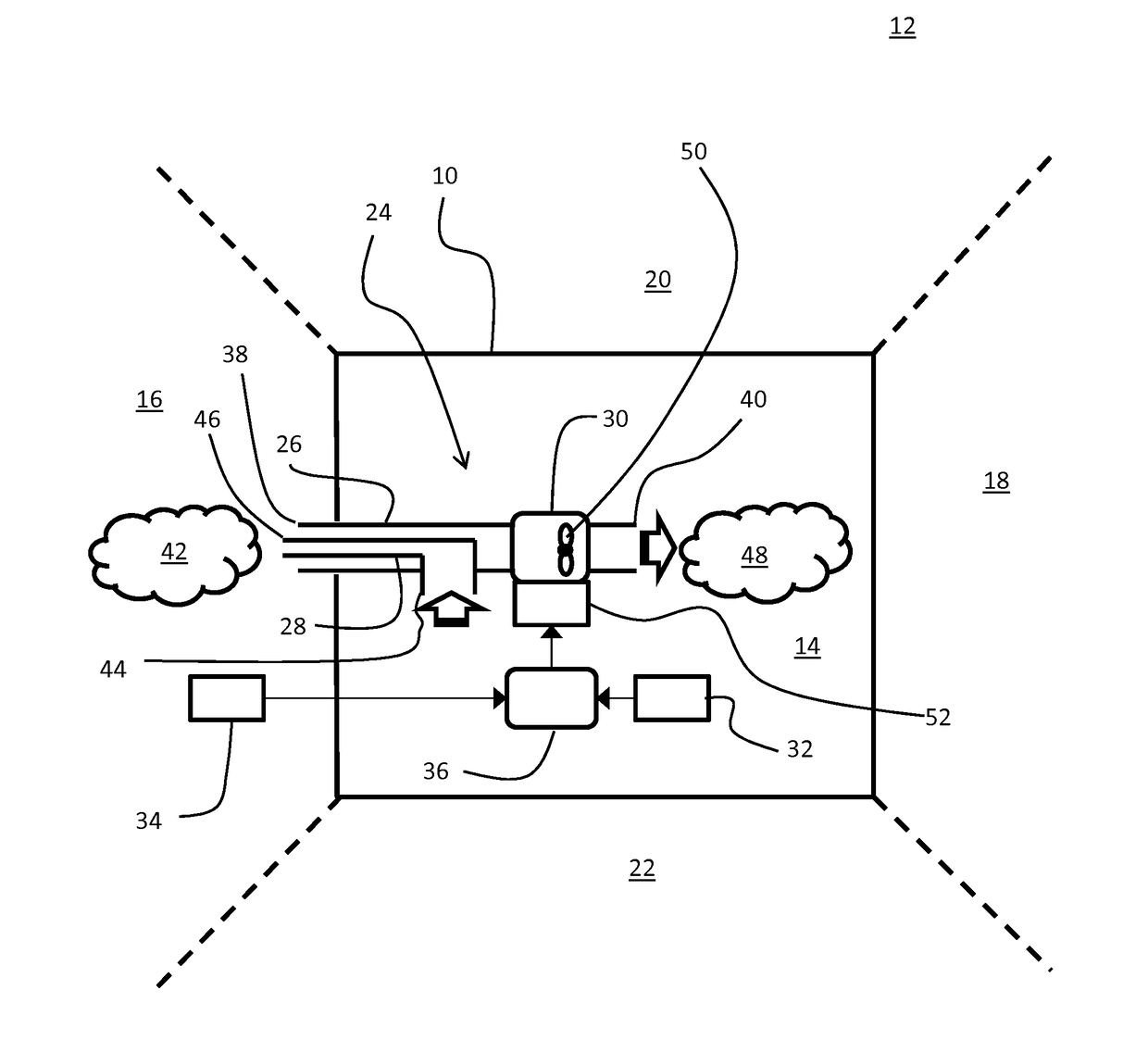
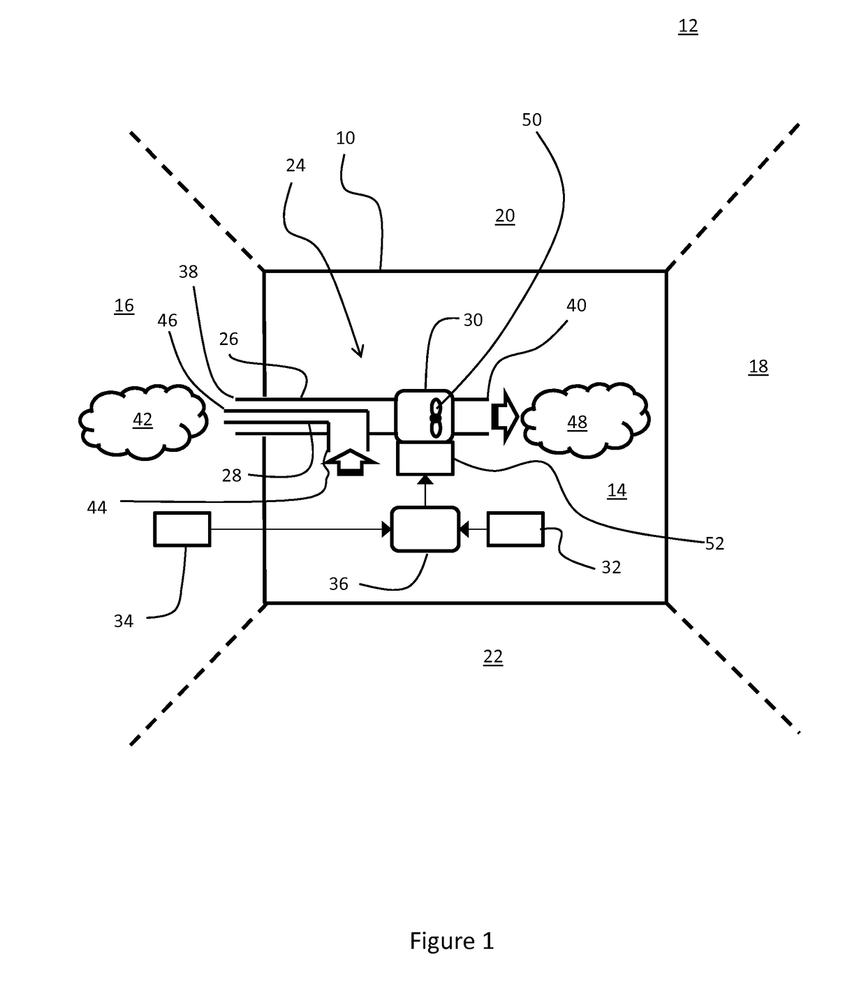
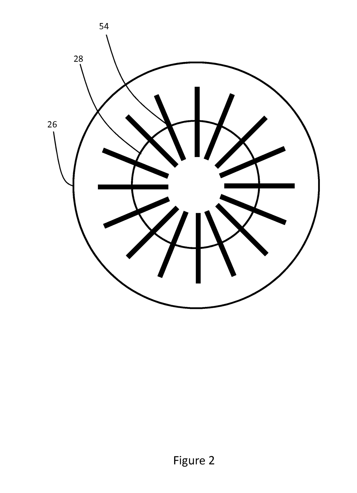
[0044]With reference to FIG. 1 and FIG. 3, a vehicle 10 includes a body supporting a plurality of doors and windows (not shown). The vehicle defines a vehicle exterior 12 and a cabin interior 14 since the body of the vehicle is substantially hermetically sealed unless the doors and / or windows are open. When the vehicle 10 is stationary, the exterior of the vehicle 12 is at a substantially constant pressure. This of course is subject to factors such as local wind speeds and temperature variations around the vehicle 10. However, to all intents and purposes the pressure around the vehicle exterior 12 is substantially constant.

[0045]During motion of the vehicle 10, pressure variations exist around an exterior surface of the vehicle 10. These changes in pressure are due to dynamic effects. For instance, local air velocities around the exterior surface of a vehicle 10 change due to differences in shape and contours thereof. An increase in local velocity can result in a decrease in local p...


PUM


Abstract

The present invention relates to a ventilation system 24 for a land vehicle 10. The ventilation system 24 comprises an inlet duct 26 for allowing exterior air to enter a cabin of the vehicle. The inlet duct 26 has a source port 38 located at an exterior of the vehicle 10 and the inlet duct 26 also has an exhaust port 40 located within a cabin of the vehicle 10. The ventilation system 24 has an outlet duct 28 for allowing interior air to exit the cabin of the vehicle 10. The outlet duct 28 has a source port 44 located within the cabin of the vehicle 10 and the outlet duct 28 also has an exhaust port 46 located at an exterior of the vehicle. The ventilation system 24 has an air propulsion element to cause selectively an airflow between the cabin interior and the vehicle exterior; wherein the source port 38 of the inlet duct 26 and the exhaust port 46 of the outlet duct 28 are collocated in a zone of substantially equivalent dynamic pressure, in-use.

Description

TECHNICAL FIELD[0001]The present disclosure relates to a ventilation system for a vehicle, particularly but not exclusively a land vehicle. Aspects of the invention relate to a ventilation system, a land vehicle, and a method of ventilating a vehicle.BACKGROUND[0002]A land vehicle, such as a car or other like, has an outer shell including a body and various doors and windows. The shell divides a vehicle exterior from a cabin interior. When the windows and doors are shut, the shell hermetically seals the cabin interior from the vehicle exterior. In order to provide an air flow through the car, the car includes a ventilation system.[0003]A typical ventilation system includes an inlet duct and an outlet duct. In order to promote air flow through the duct to ventilate the car, a source port of the inlet duct is located in a high pressure region of the vehicle exterior and an exhaust port of the outlet duct is located in a low pressure region of the vehicle exterior.[0004]When a car is s...

Claims


Application Information

Patent Timeline
IPC IPC(8): B60H1/00B60H1/24
CPCB60H1/00564B60H1/008B60H1/00785B60H1/00321B60H1/248B60H1/00828B60H1/241B60H1/26B60H1/00021B60H1/00849
Inventor BELOE, NEIL
Owner JAGUAR LAND ROVER LTD
Learn More