

Apparatus and method for calibrating a weigh-in-motion sensor
a technology of weigh-in motion and apparatus, which is applied in the field of apparatus for calibrating a weigh-in-motion sensor, can solve the problems of different quality of installation, road wear, and roadway affecting the quality parameters, and achieve the effect of high accuracy, high accuracy, and high accuracy
Active Publication Date: 2018-08-30
KISTLER HLDG AG
View PDF3 Cites 4 Cited by
- Summary
- Abstract
- Description
- Claims
- Application Information
AI Technical Summary
Benefits of technology
The patent describes a calibration method for a WIM sensor installed in a roadway. The method uses a position sensor to accurately measure the position of the WIM sensor relative to the installation site. A reference force is then introduced along the calibration path using an applicator, allowing the position to be detected with high accuracy. This method allows for accurate detection of the WIM sensor installation site and ensures the quality of the installation. It is able to account for elevation or depression in the road surface at the installation site and achieve a position resolution within the millimeter range. Overall, the invention improves the accuracy and efficiency of the calibration process for WIM sensors.
Problems solved by technology
The WIM sensor is inserted in the roadway on-site which leads to differences in a quality of installation.
However, also different installation depths of WIM sensors underneath a surface of the roadway affect the quality parameters thereof.
The road surface is subject to wear.
Potholes and ruts in the roadway in the vicinity of the WIM sensor may invalidate the calibration function in which case the calibration function will become inaccurate.
Then, the calibration process must be repeated making it time-consuming.
However, this requires a calibration of the calibration vehicle itself, a time-consuming and costly process.
Method used
View moreImage
Smart ImageViewing Examples

Examples
first embodiment
[0021]FIG. 6 shows a perspective view of a portion of a carriage comprising an applicator equipped with wide wheels of the apparatus according to FIGS. 1 to 4;
second embodiment
[0022]FIG. 7 shows a perspective view of a portion of a carriage comprising an applicator equipped with narrow wheels of the apparatus according to FIGS. 1 to 4;
third embodiment
[0023]FIG. 8 shows a perspective view of a portion of a carriage comprising an applicator in the shape of a punch of the apparatus according to FIGS. 1 to 4; and
[0024]FIG. 9 shows a schematic representation of the apparatus according to FIGS. 1 to 4 for calibrating a WIM sensor inserted in a roadway.
Login to View More PUM
 Abstract
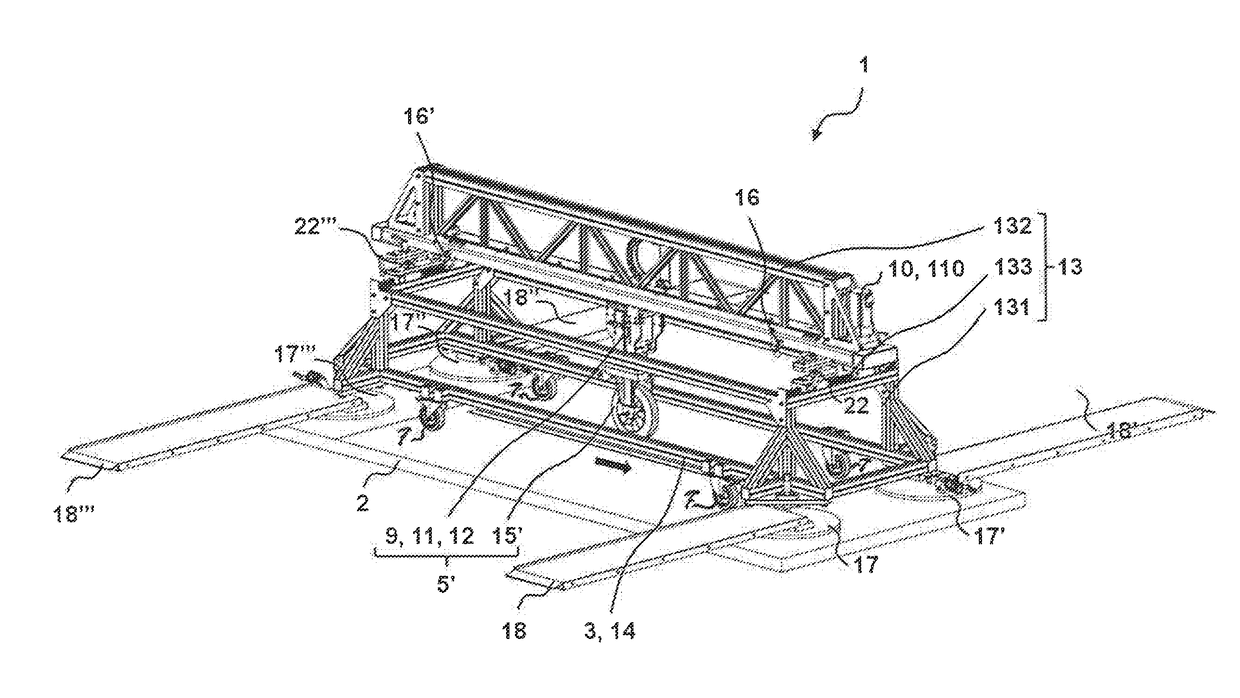
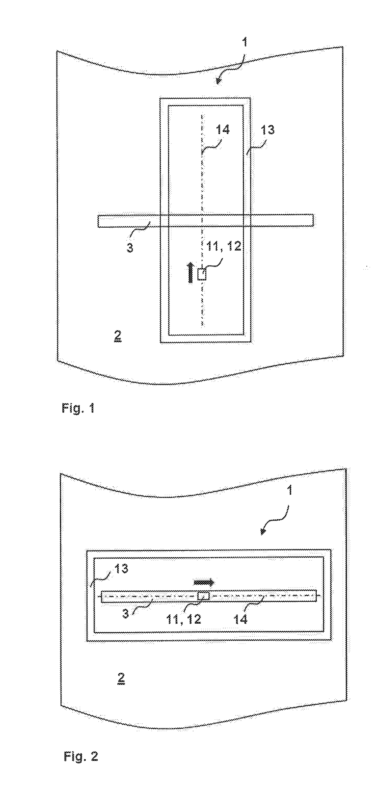
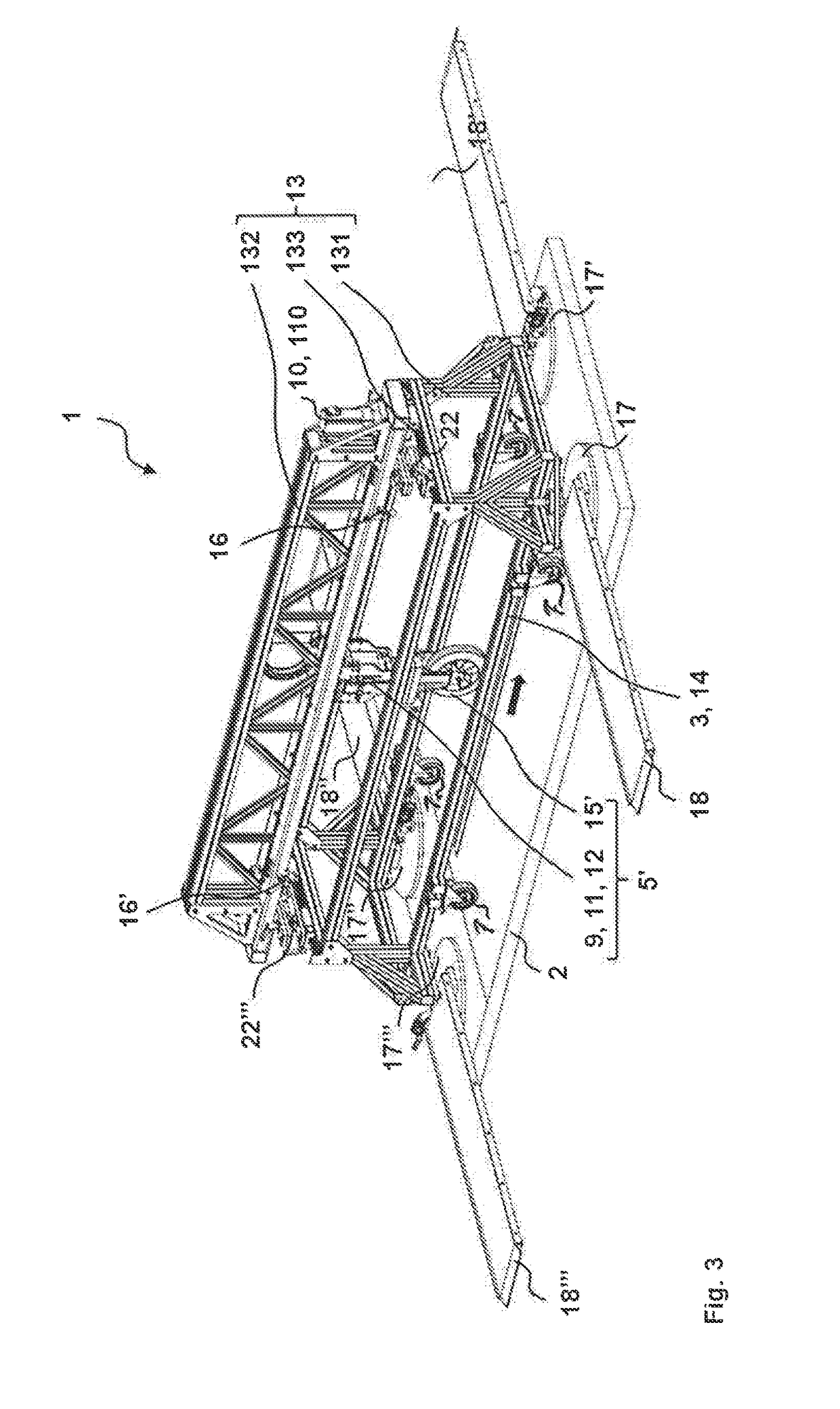
An apparatus for calibrating a weigh-in-motion (WIM) sensor embedded in a roadway includes an actuator, an applicator, a force sensor disposed between the actuator and the applicator, and a carriage supporting the actuator, the applicator and the force sensor, which carriage is selectively movable on a longitudinal support carried by a frame. The apparatus also includes a drive unit to move the applicator along the longitudinal support as well as a position sensor that detects a position of the calibration path relative to the WIM sensor. According to a method for calibrating a WIM sensor, the frame is positioned to straddle the WIM sensor. The applicator introduces along the calibration path at a succession of different positions, a reference force that is measured by the WIM sensor and the force sensor, and these measurements are compared to generate a calibration.
Description
TECHNICAL FIELD[0001]The invention relates to an apparatus for calibrating a weigh-in-motion (WIM) sensor that is inserted in a roadway and includes at least one force sensor that detects a reference force and that is calibrateable using the reference force. The invention also relates to a method for calibrating a WIM sensor that is inserted in a roadway and includes at least one force sensor that detects a reference force and that is calibrateable using the reference force.BACKGROUND OF THE INVENTION[0002]A WIM sensor is a force transducer that can be inserted in a roadway. By means of the WIM sensor inserted in the roadway it is possible to monitor a weight force of a vehicle travelling on the roadway. From the weight force measured, information with respect to diverse traffic parameters such as wheel load, axle load, total weight, tire pressure of the moving vehicle can be determined. In many cases, the WIM sensor is a piezoelectric force transducer measuring the weight force of ...
Claims
Login to View More Application Information
Patent Timeline
 Patent Type & AuthorityApplications(United States)
IPC IPC(8): G01G23/01G01G19/03G01G3/13
CPCG01G23/01G01G19/035G01G3/13G01G19/024G01G21/26E01F11/00G01G19/02G01G19/00
InventorWUHRMANN, THOMASHOFMANN, ADRIANAESCHBACHER, MANUEL
OwnerKISTLER HLDG AG