
STED super-resolution microscope and adjusting method based on a first-order Bessel beam

a super-resolution, beam-based technology, applied in the field of microscope techniques, can solve the problems of complex operations, unsuitable for high scattering samples, and inability to rapidly reduce the resolution deep in the specimen, and achieve the effect of less expensiv

Active Publication Date: 2018-08-30
PEKING UNIV
View PDF0 Cites 20 Cited by
  • Summary
  • Abstract
  • Description
  • Claims
  • Application Information

AI Technical Summary

Benefits of technology

The patent describes a new system and method for deep super-resolution imaging that uses a depletion beam with anti-diffractive and self-healing properties. This beam is able to maintain its donut shape deep in the specimen, allowing for higher resolution imaging without the need for any active adjustments. Compared to other methods, this system is simpler and less expensive. Overall, the technical effects of this patent are improved deep super-resolution imaging without the need for active adjustments and reduced complexity and cost.

Problems solved by technology

The technical problem addressed in this patent is how to improve the resolution of stimulated emission depletion (STED) microscopy, which is a technique used in biological imaging and other fields. The conventional method uses two laser beams, but the shape of the depletion beam can be distorted due to spherical aberration and scattering distortion, which can result in rapid decrease of resolution at large image depths. The patent seeks to address this problem by developing a new method that compensates for spherical aberration and is suitable for high scattering samples.

Method used


Image

  • STED super-resolution microscope and adjusting method based on a first-order Bessel beam
  • STED super-resolution microscope and adjusting method based on a first-order Bessel beam
  • STED super-resolution microscope and adjusting method based on a first-order Bessel beam

Examples


implementation example one

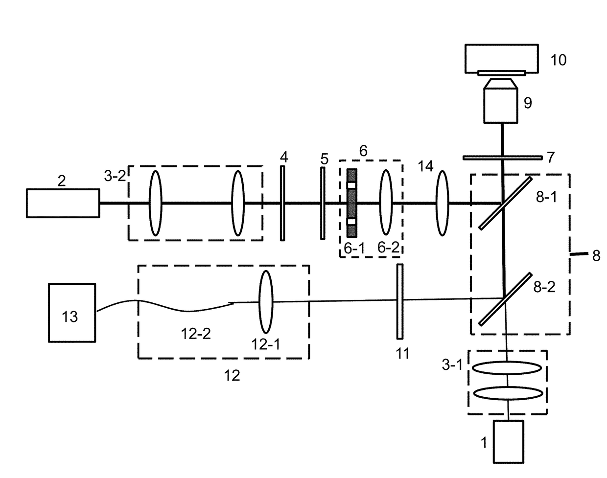
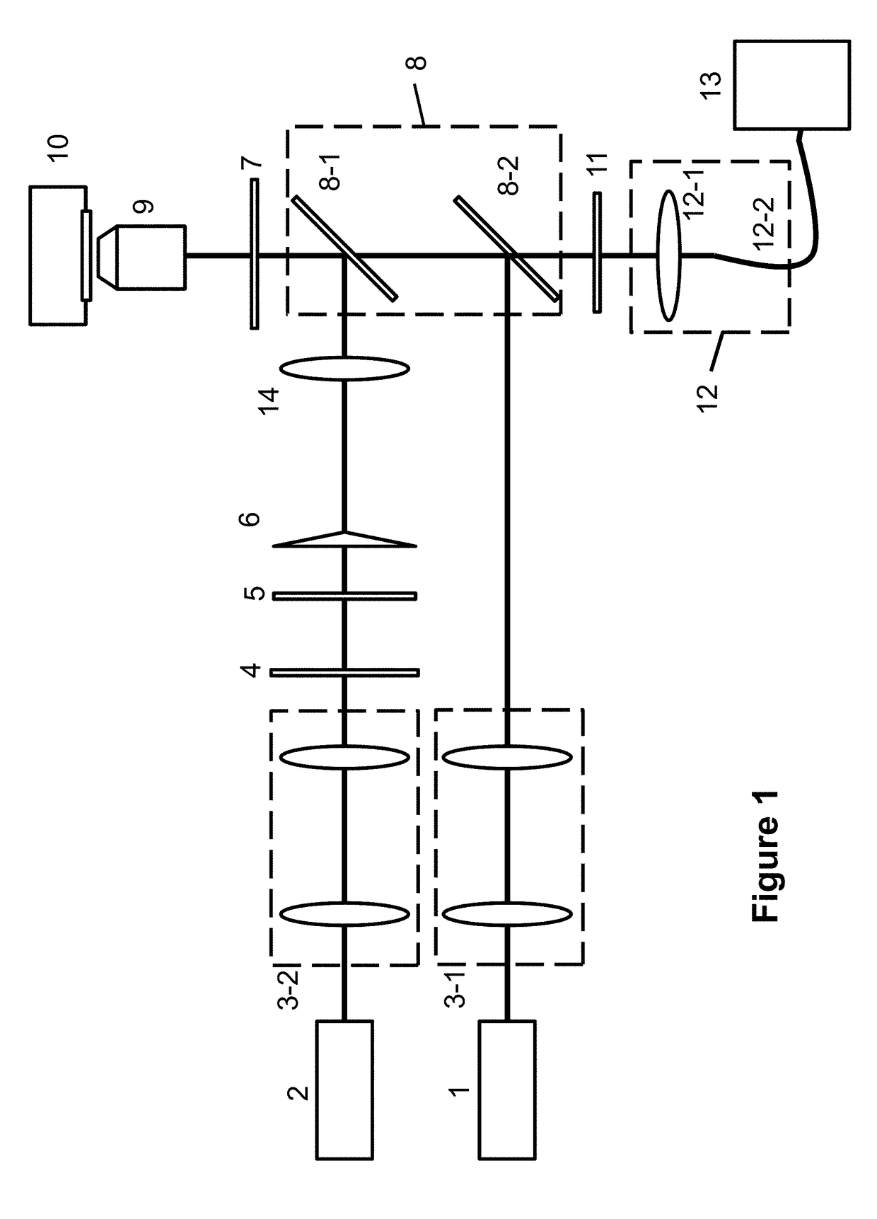
[0030]Referring to FIG. 1, a STED super-resolution microscopy based on the first-order Bessel beam includes: an excitation laser 1, a depletion laser 2, an excitation collimating and beam expanding system 3-1; a depletion collimating and beam expanding system 3-2; a vortex phase plate 4; a half-wavelength plate 5; a Bessel beam generating system 6; a depletion beam focusing lens 14; a beam combining system 8; an objective lens 9; a piezoelectric scanning system 10; a filter 11; a signal collecting system 12, and a single-photon detecting system 13. The excitation laser 1 fills the entrance of the objective lens 9 after the excitation collimating and beam expanding system 3-1. The linear-polarization depletion laser 2 passes through the depletion collimating and beam expanding system 3-2, the vortex phase plate 4, the half-wavelength plate 5, the Bessel beam generating system 6, and the depletion beam-focusing lens 14 in turns. Then it is combined with the excitation beam by the beam...

implementation example two

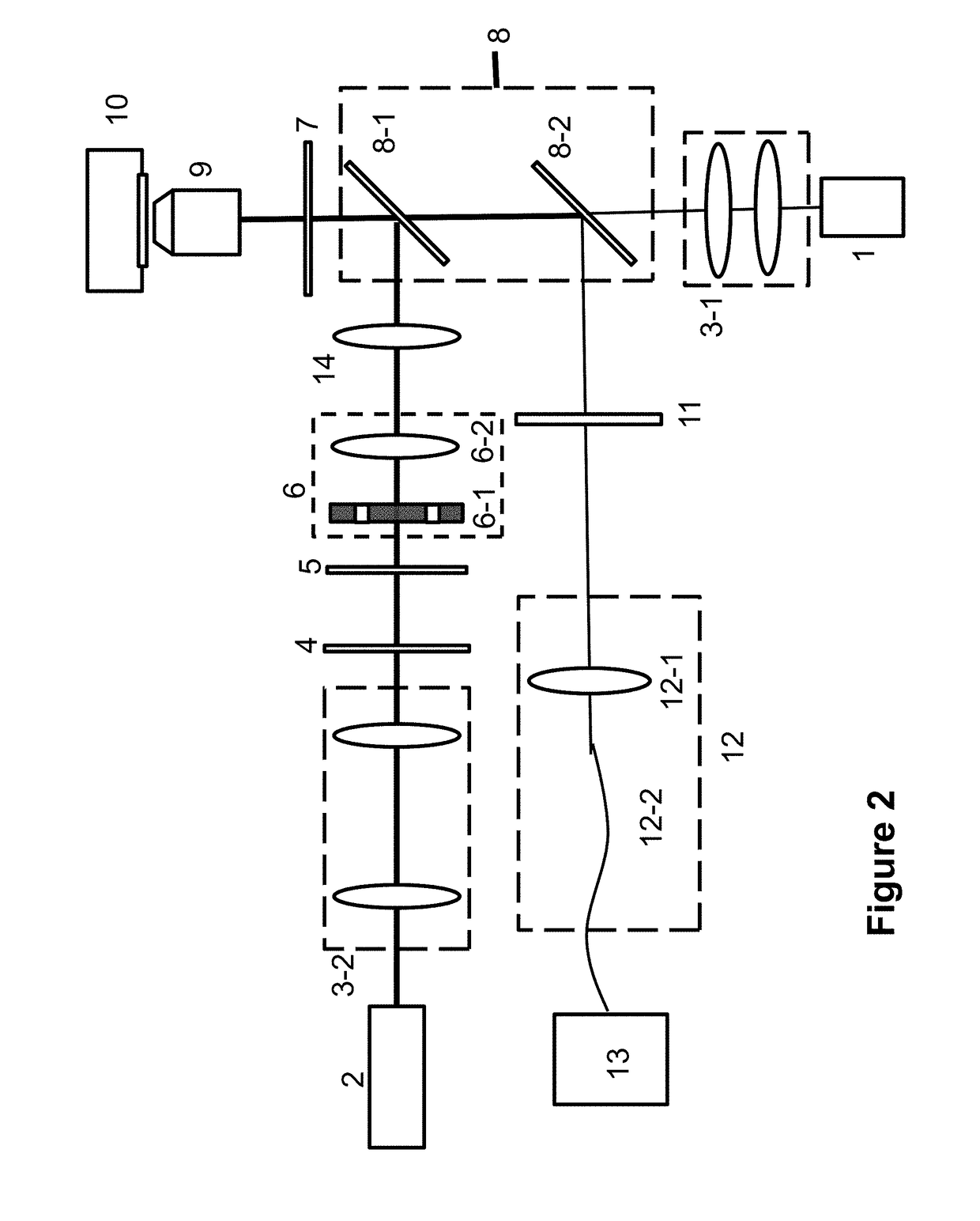
[0035]Referring to FIG. 2, the Bessel beam generating system 6 includes an annular mask 6-1 and a lens 6-2. We can adjust the distance between the lens 6-2 and the depletion beam-focusing lens 14 to make sure that the excitation focal spot to locate at the center of the first-order Bessel depletion beam. Then the excitation and depletion focal spot can be made to overlap precisely using the beam combining system 8.

[0036]In the current example, the excitation beam and depletion beam are orthogonal to each other; and the depletion beam and the signal beam are parallel to each other. The first dichroic mirror 8-1 is totally reflective for the depletion beam and totally transparent to the excitation beam and signal beam. The second dichroic mirror 8-2 is totally reflective for the signal beam and totally transparent to the excitation beam. In this condition, the depletion beam reflected by the first dichroic mirror 8-1 is combined with the excitation beam that has passed through the fir...


PUM


Abstract

“A stimulated-emission-depletion (STED) super-resolution microscope includes an excitation light source, a depletion light source , an excitation light expanded beam alignment system, a spiral-shaped phase plate, a Bessel beam generating system, a depletion light focus lens, a beam combination system , an objective lens, a piezoelectric scanning system, a filter, a signal collection system, and a single-photon detector. The depletion light can be a first-order Bessel beam. The depletion light has anti-scattering and self-healing characteristics, and is capable of keeping the spot shape at a deeper position of a sample, thereby improving image resolution in the deep region of the sample. Compared to conventional STED super resolution microscope of deep-layer imaging using an adjustable correction collar, the present invention is simpler in experimental operations and does not require active adjustments. Compared to adaptive optical systems, the present experimental apparatus is simpler and less expensive.

Description


Claims


Application Information

Patent Timeline
Owner PEKING UNIV
Learn More