Electrical power generation system for a directed energy weapon and method

a technology of directed energy and power generation system, which is applied in the direction of efficient propulsion technology, machines/engines, light and heating apparatus, etc., can solve the problem that directed energy weapons require large amounts of electricity

Inactive Publication Date: 2018-09-06
HAMILTON SUNDSTRAND CORP
View PDF7 Cites 6 Cited by
  • Summary
  • Abstract
  • Description
  • Claims
  • Application Information

AI Technical Summary

Problems solved by technology

Directed energy weapons require large amounts of electricity.

Method used


Image

  • Electrical power generation system for a directed energy weapon and method
  • Electrical power generation system for a directed energy weapon and method
  • Electrical power generation system for a directed energy weapon and method

Examples


Embodiment Construction

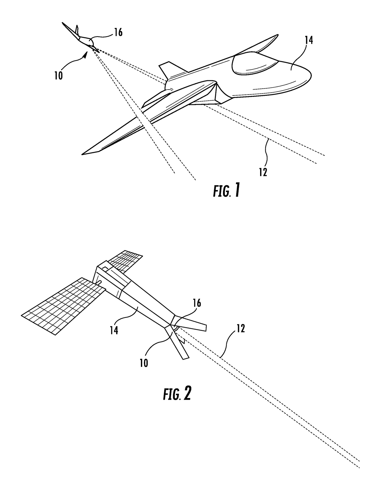
[0013]Referring to FIGS. 1 and 2, embodiments of a directed energy weapon are illustrated. In the illustrated embodiments, the directed energy weapon comprises a directed energy system 10 that facilitates generation of a directed energy weapon, such as a laser beam 12, onboard a vehicle 14 and guided control of the laser beam 12 away from the vehicle 14. The directed energy system 10 is beneficial in numerous applications, such as tactical weaponry, for example. As such, the embodiments described herein are advantageously operated on vehicles that require operation in environments which do not have atmospheric oxygen (i.e., oxygen gas) present. For example, the vehicle 14 may be a spacecraft (FIG. 1) or a high altitude aircraft (FIG. 2). Additionally, the vehicle 14 may be an undersea vessel that is completely submerged in fluid, such that oxygen gas is not readily available from the surrounding environment.

[0014]Although a laser beam 12 is illustrated and referenced herein, it is t...


PUM


Abstract

An electrical power generation system for a directed energy weapon includes a fuel pump configured to disperse a liquid fuel. Also included is an oxidizer pump configured to disperse a liquid oxidant. Further included is a combustor fluidly coupled to the fuel pump and the oxidizer pump to receive the liquid fuel and the liquid oxidant for combustion therein to form a combustion mixture. Yet further included is a turbine fluidly coupled to the combustor to receive the combustion mixture to generate mechanical energy. Also included is a generator operatively coupled to a rotor shaft of the turbine to convert the mechanical energy to electrical power for the directed energy weapon.

Description

BACKGROUND OF THE DISCLOSURE[0001]The embodiments herein generally relate to directed energy weapons and, more particularly, to an electrical power generation system for such weapons, as well as a method of generating electrical power for such weapons.[0002]Directed energy weapons require large amounts of electricity. Due to the desire to place directed energy weapons on airborne platforms, there is a desire to reduce the size of the directed energy weapons systems so they may be placed on smaller aircraft and even space-based platforms. Challenges associated with implementation of directed energy weapons are present in applications that operate at high altitude (e.g., aircraft and spacecraft) based on the need for an electrical power generation system to operate in locations where there is little to no oxygen present. These challenges are unique to applications that are not land-based or on above surface ships, as these applications typically have ample space for large electrical p...

Claims


Application Information

Patent Timeline
Patent Type & Authority Applications(United States)
IPC IPC(8): F01D15/10F41H13/00F02C6/00F02C7/12F23K5/14
CPCF01D15/10F41H13/0043F02C7/12F23K5/142F05D2220/76F23C2900/03001F02C6/00F02C3/20F02C3/24Y02T50/60
Inventor HIMMELMANN, RICHARD A.BAUCH, TIMOTHY A.PAPAS, PAUL
Owner HAMILTON SUNDSTRAND CORP
Why Eureka
Try Eureka