
System, device and method for automatic commissioning of application control systems

a technology of application control system and automatic commissioning, applied in the field of application control system, can solve the problems of complex control instructions, cumbersome manual labor, and inability to achieve complex control instructions, and achieve the effect of reliably commissioning application devices

Pending Publication Date: 2018-09-06
SIGNIFY HLDG BV
View PDF3 Cites 3 Cited by
  • Summary
  • Abstract
  • Description
  • Claims
  • Application Information

AI Technical Summary

Benefits of technology

The present invention provides an improved system for reliably commissioning application devices within an application control network. The system should scale well with the size of the network without creating large overhead concerning the managing information and maintenance work. The commissioning device can be an autonomous vehicle, a ground based vehicle, or a marine vessel, and it can be positioned manually or automatically. The base station can determine the position of the application device based on an analysis of a network graph upon occurrence of the reaction of the first application device. The commissioning device can also use an imaging module, a situational awareness module, and a communication interface to interact with the base station and verify the reaction of the application device. The system can also use directional antennas for communication with the base station to extend the range of the wireless data link.

Problems solved by technology

However, in modern application control systems more complex control instructions are desired.
This information may require cumbersome manual labor.

Method used


Image

  • System, device and method for automatic commissioning of application control systems
  • System, device and method for automatic commissioning of application control systems
  • System, device and method for automatic commissioning of application control systems

Examples


Embodiment Construction

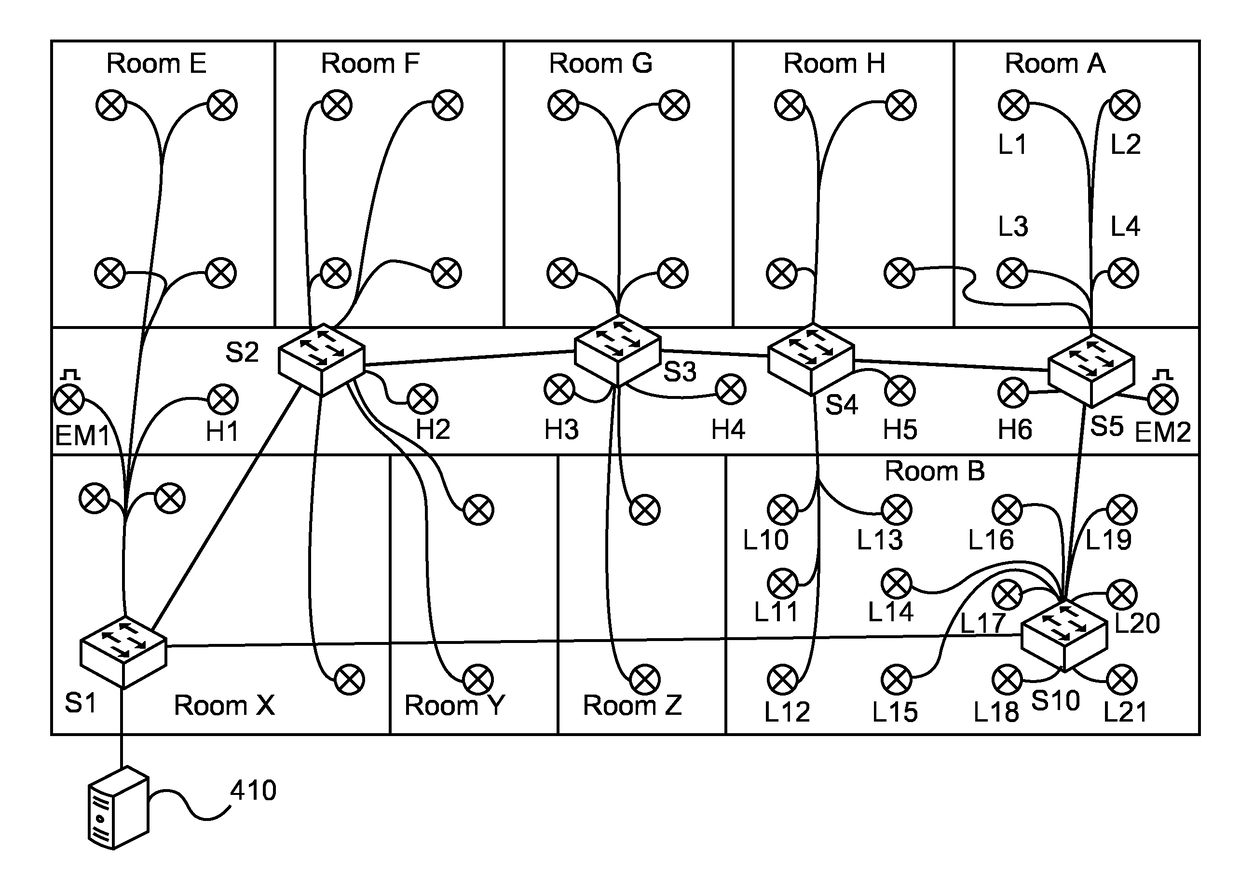
[0056]Embodiments are now described based on a lighting control system. However, it is to be understood that the embodiments are not restricted to lighting control systems. The person skilled in the art will appreciate that the methods and devices may be exploited in any other control system having a similar topology.

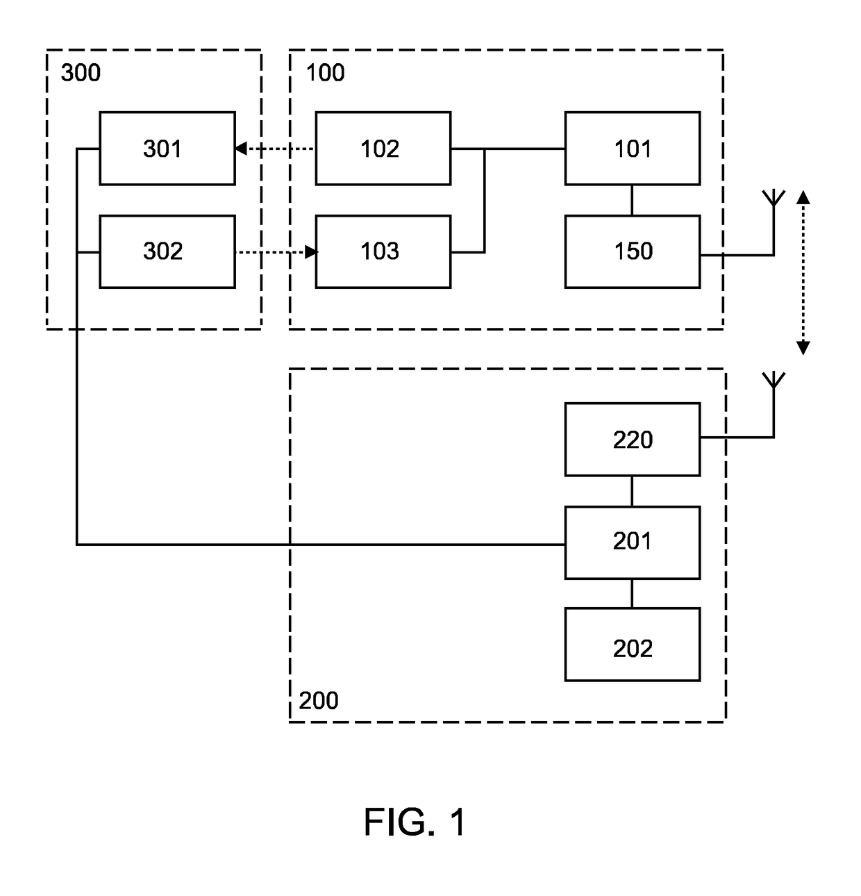
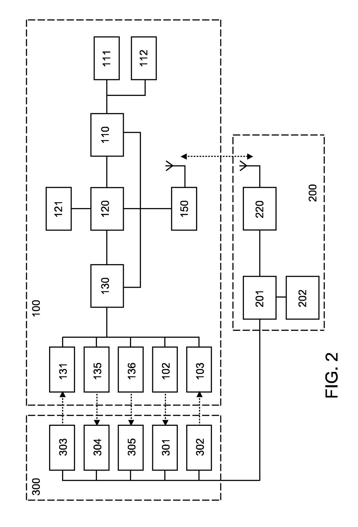
[0057]FIG. 1 illustrates a first embodiment of the present invention. A commissioning device 100 maintains a data-link 150 / 220 to a commissioning base station 200 during the commissioning process. Wherein FIG. 1 illustrates the data link as RF data link, the data link may also be realized as IR, VLC, FSO, acoustic, etc. The commissioning base station 200 implements a SDL system 201 which maintains a building and lighting plan 202. The SDL system 201 is connected to a lighting control network 300 to record data from sensors 301 and to send commands to trigger actuators 302. The commissioning device 100 can interact with the lighting control network 300 as well, to trigge...


PUM


Abstract

The present invention provides an improved system, device and method for reliably commissioning application devices within an application control network that scales well even with large installations of the respective application control systems. Instead of relying on a direct physical identification of the application devices installed at a specific position, e.g. in a building, the commissioning is based on feedback on trigger events and relative positions of the application devices. In a system comprising a commissioning device and a commissioning base station having access to an application plan the commissioning device is communicatively connected with the commissioning base station and is adapted to determine a relative position of a first application device that is communicatively coupled with an application control network. The commissioning device is further adapted to interact with the commissioning base station to trigger a reaction of the first application device and to verify that the reaction occurred. The system is adapted to create a corresponding application plan entry for the first application devices upon verification of the reaction.

Description

FIELD OF THE INVENTION[0001]The present invention relates to the field of application control systems, in particular to the commissioning process of application control systems such as—but not limited to—lighting control systems.BACKGROUND OF THE INVENTION[0002]In recent years application systems, such as—but not limited to lighting systems, environmental control systems etc, are controlled via application control networks using a control plan providing information about the presence and interaction of the application devices of the application system.[0003]From US 2014 / 0365018 A1 a system for controlling a plurality of appliances within a building is known, wherein the plurality of appliances are controlled by an external server which determines one or more appliances to be present in the same room and controls the respective appliances based on environmental information previously received from the plurality of appliances.[0004]Application devices, such as sensors and actuators co...

Claims


Application Information

Patent Timeline
IPC IPC(8): H04L12/28H05B37/02G05B15/02
CPCH04L12/2814H04L12/281H04L12/282H05B37/0272G05B15/02G05B2219/2642H05B47/19H05B47/195H05B47/199G05B2219/26
Inventor KAAG, BJORN CHRISTIAAN WOUTERWOUTERS, CORNELIS BERNARDUS ALOYSIUS
Owner SIGNIFY HLDG BV
Learn More