

Illuminated stowage bin assemblies within vehicles
- Summary
- Abstract
- Description
- Claims
- Application Information
AI Technical Summary
Benefits of technology
Problems solved by technology
Method used
Image

Examples
Embodiment Construction
[0002]Embodiments of the present disclosure generally relate to interior cabins within vehicles, such as commercial aircraft, and, more particularly, to electronic stowage bin control systems and methods within interior cabins of vehicles.
BACKGROUND OF THE DISCLOSURE
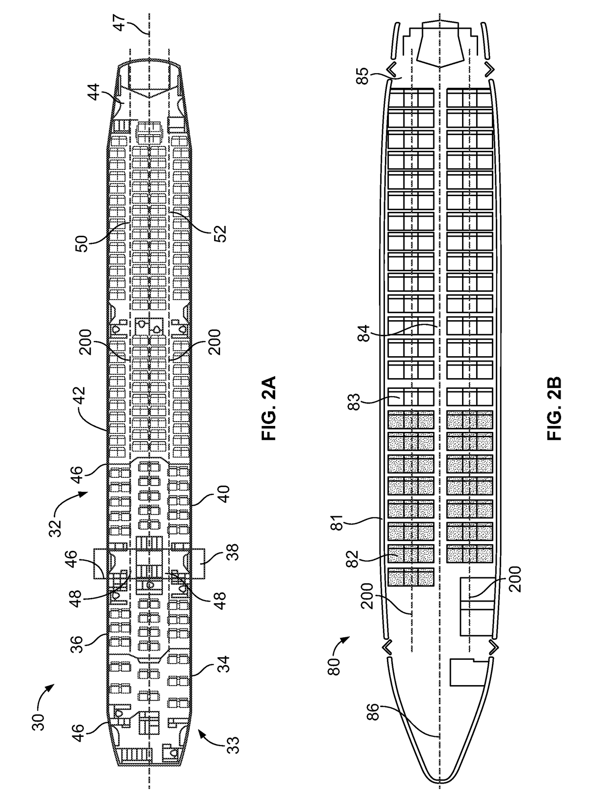
[0003]Commercial aircraft typically include an interior cabin that may be divided into numerous sections. A cockpit is generally separated from a passenger cabin, which may include a first class section, a business class section, and a coach section. The passenger cabin may also include one or more work areas for flight personnel, such as galleys, which may include food and beverage storage structures. One or more aisles pass through the passenger cabin and connect each of the passenger sections to one or more paths to one or more doors of the aircraft.
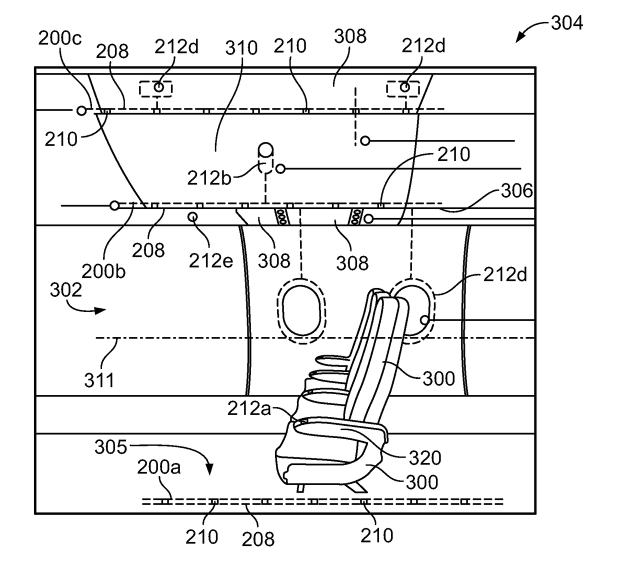
[0004]Overhead stowage bins are typically positioned above rows of seats within a commercial aircraft. Each overhead stowage bin is configured to be moved between an open ...
PUM
 Abstract
Description
Claims
Application Information