Dynamically positioned liquid mud plant vessel

a plant vessel and dynamic positioning technology, applied in special purpose vessels, steering initiations, instruments, etc., can solve the problem of more difficult logistics for supplying rigs with supplies

Inactive Publication Date: 2018-09-13
ZENTECH
View PDF7 Cites 1 Cited by
  • Summary
  • Abstract
  • Description
  • Claims
  • Application Information

AI Technical Summary

Problems solved by technology

As the industry moves further away from the shore (into deeper waters) in pursuit of petroleum, the logistics of supplying a rig with supplies becomes more difficult due the distance betwe...

Method used


Image

  • Dynamically positioned liquid mud plant vessel
  • Dynamically positioned liquid mud plant vessel
  • Dynamically positioned liquid mud plant vessel

Examples


Embodiment Construction

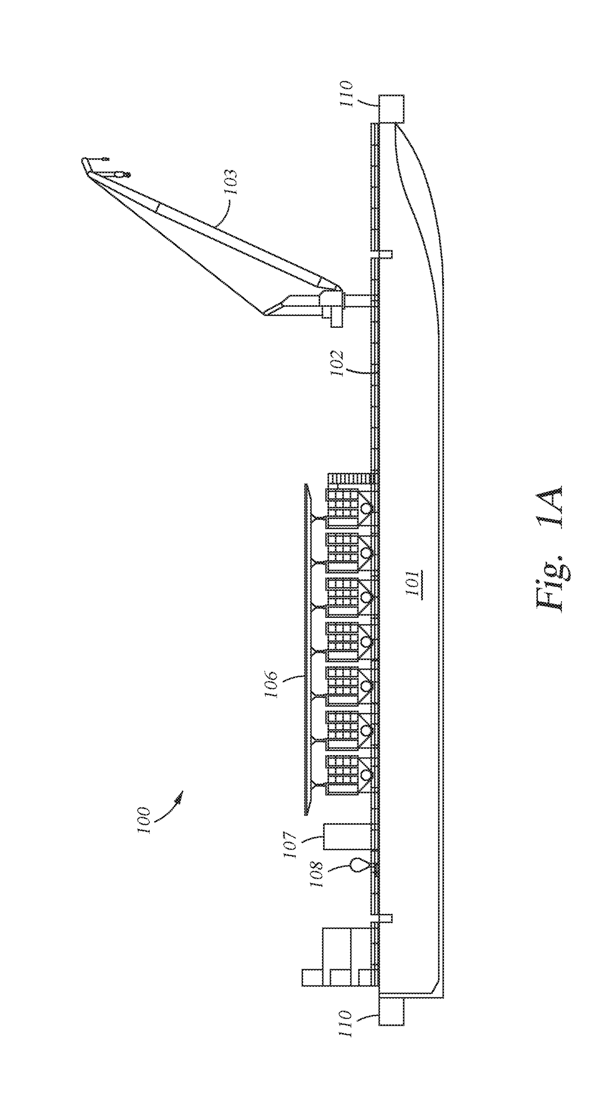
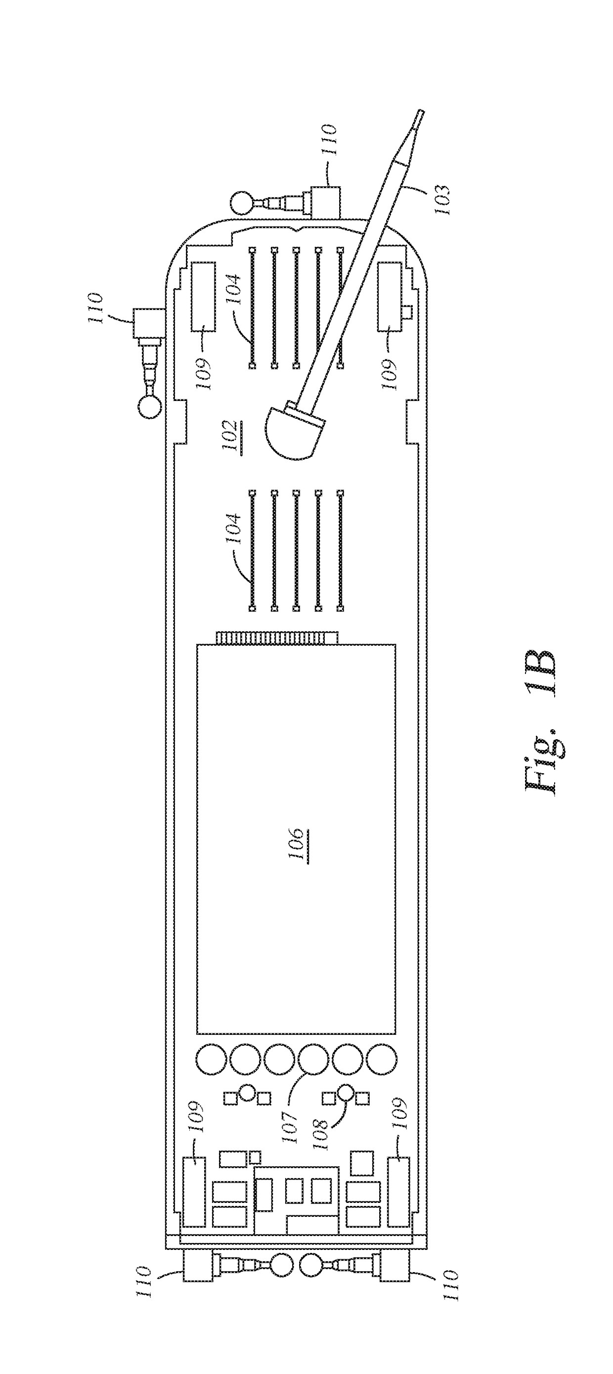
[0013]The present disclosure generally relates to an apparatus for storing, treating, and making up of various drilling fluids onboard a dynamically positioned vessel, such as a barge, boat, or shop. In particular, the present disclosure relates to a liquid mud plant (LMP) supporting any offshore drilling rig or platform from a vessel in closer proximity to that rig. Additionally, the present disclosure relates to the process by which the liquid mud plant is in closer proximity to the drilling, which is derived from the dynamical positioning capability of the liquid mud plant vessel.

[0014]FIG. 1A is a schematic side view of a dynamically positioned liquid mud plant vessel (DPLMPV) 100. FIG. 1B is a schematic top plan view of the DPLMPV 100 of FIG. 1A. The DPLMPV 100 includes a hull 101 having a deck 102. The DPLMPV 100 also includes a crane 103, one or more pipe racks 104 (two sets are shown), and a liquid mud plant 105 positioned on the deck. The liquid mud plant 105 includes one o...


PUM


Abstract

The present disclosure generally relates to an apparatus for storing, treating, and making up of various drilling fluids onboard a dynamically positioned vessel, such as a barge, boat, or shop. In particular, the present disclosure relates to a liquid mud plant (LMP) supporting any offshore drilling rig or platform from a vessel in closer proximity to that rig. Additionally, the present disclosure relates to the process by which the liquid mud plant is in closer proximity to the drilling, which is derived from the dynamical positioning capability of the liquid mud plant vessel.

Description

CROSS-REFERENCE TO RELATED APPLICATIONS[0001]This application claims benefit of U.S. provisional patent application Ser. No. 62 / 468,865, filed Mar. 8, 2017, which is herein incorporated by reference.BACKGROUNDField[0002]Embodiments of the present disclosure generally to an apparatus for storing, treating, and making up of various drilling fluids onboard a dynamically positioned vessel, such as a barge, boat, or ship.Description of the Related Art[0003]Offshore drilling rigs in search for oil and gas each have their own supply and logistics demands to allow the offshore drilling rigs to work away from the shore. As technology and the need for petroleum advances, more and more of these offshore drilling operations are moving into deep waters (e.g., greater than 500 meters water depth).[0004]Conventionally, a ‘supply base’ is set up as close as feasible to the offshore drilling operation to supply the rig or rigs with necessary daily supplies (e.g., diesel fuel, food, tubulars, drillin...

Claims


Application Information

Patent Timeline
IPC IPC(8): B63H25/42B63H25/04B63B35/44G05D1/02
CPCB63H25/42B63H25/04B63B35/4413G05D1/0208B63B2213/02B63H2025/045B63B2747/00
Inventor SHERWOOD, JOSEPHSRINIVASAN, SUNDARAMMAINI, RAMESH
Owner ZENTECH
Why Eureka
Try Eureka