

Marine subsea free-standing riser systems and methods
A standpipe and free technology, applied in the direction of drill pipe, casing, earthwork drilling and mining, etc., can solve problems such as unsolved
- Summary
- Abstract
- Description
- Claims
- Application Information
AI Technical Summary
Problems solved by technology
Method used
Image

Examples
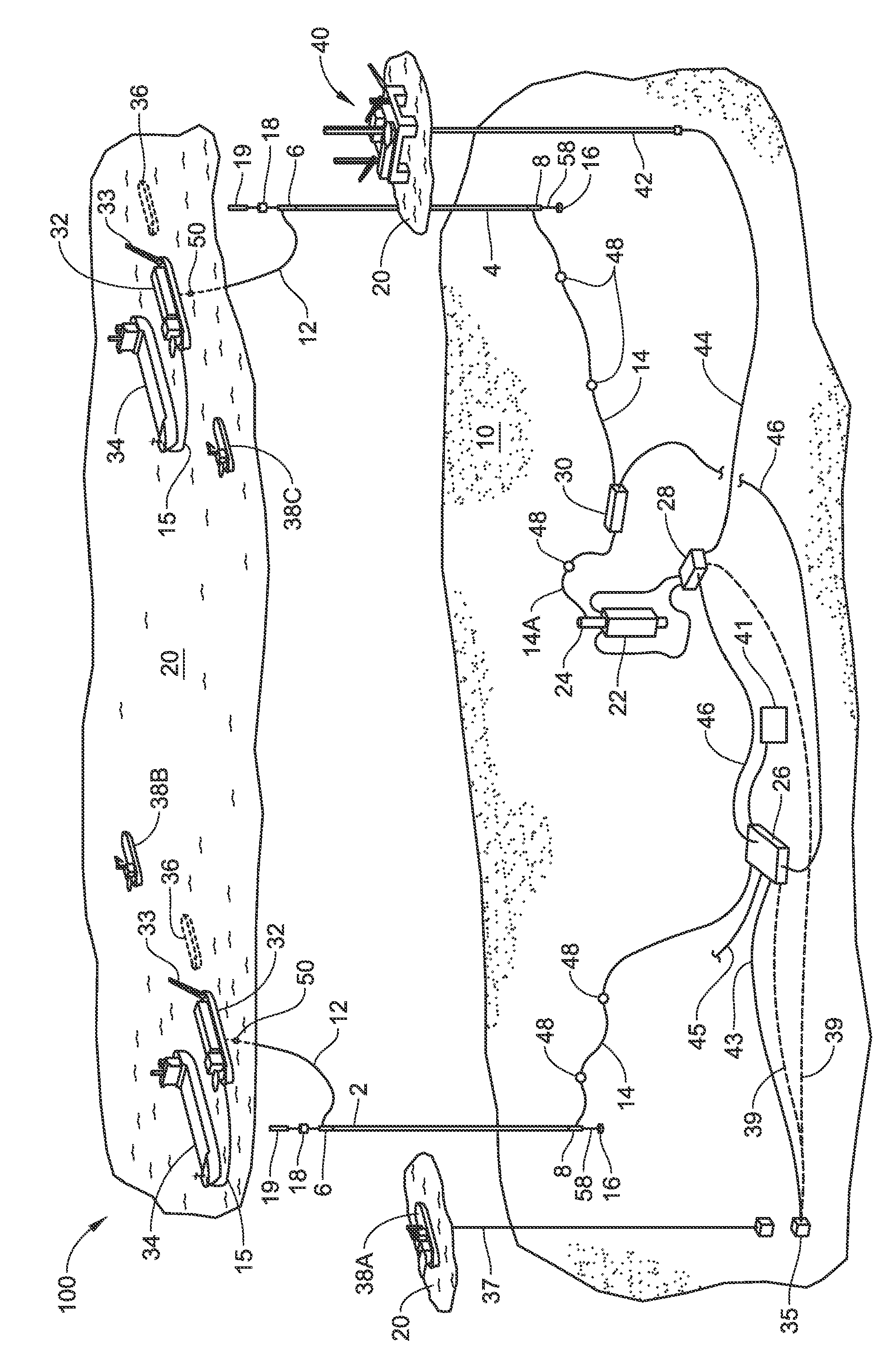
Embodiment 100
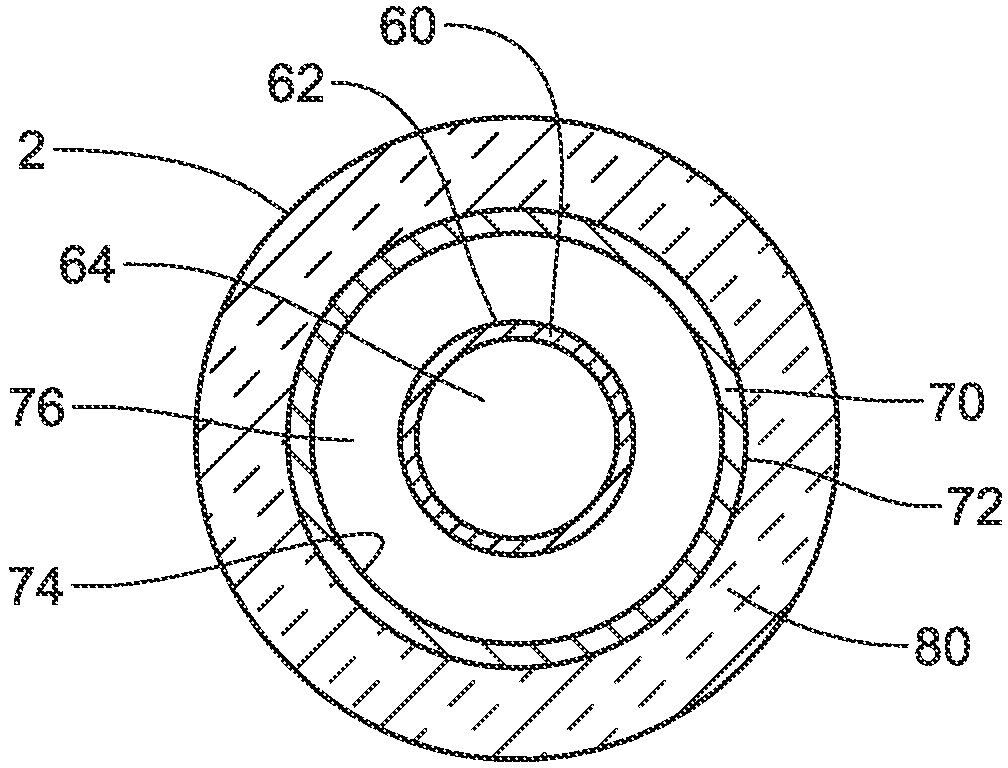
[0229] Free standing risers 2 and 4 in embodiment 100 may be a tube-in-tube design based in part on a "dry tree" riser design, wherein the annulus is filled with a flow assurance fluid (e.g., low pressure nitrogen) Air to improve liquidity assurance. While further details are set forth here, the main parts of system 100 may be:
[0230] 6 inches (15 cm) of slow wave ID flexible jumper 14 with distributed buoyancy modules 48 connected from the base of each FSR to the subsea manifold on the seabed (in the case of the first FSR (2), distributed buoyancy The module 48 may be connected to the closed process manifold (CDM) marked 26, while in the case of the second FSR (4) the decentralized buoyancy module 48 may be connected to the BOP stack manifold 30, the BOP stack Sink 30 is fluidly connected to BOP stack cap 24 via flexible jumper 14A, and to CDM 26 via flexible piece 46);
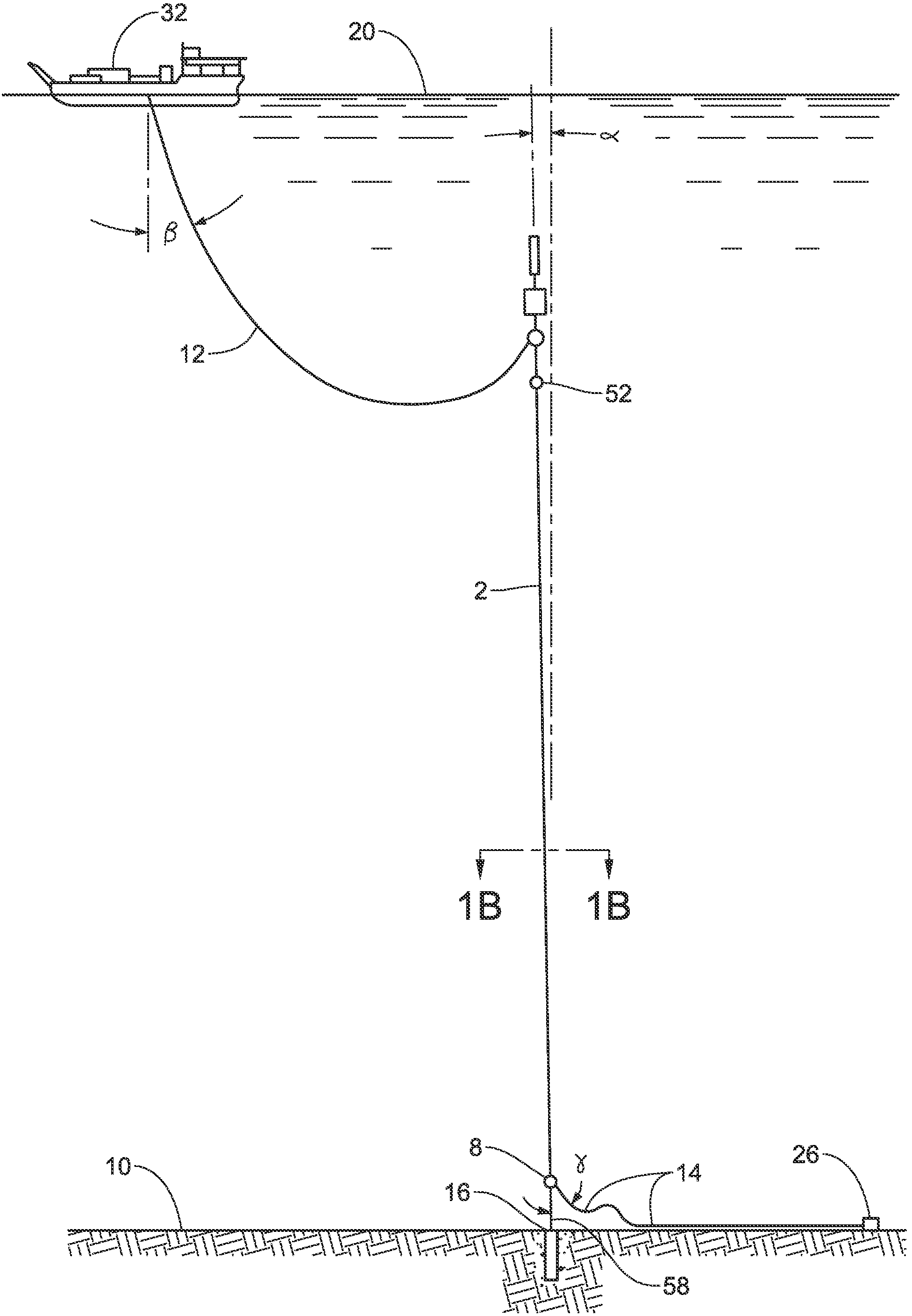
[0231] a suction pile foundation 16 and a chain rope 58 connectable to the respective bases of FSR2 a...
PUM
 Abstract
Description
Claims
Application Information