Deepwater semi-submerged drilling platform

A drilling platform and semi-submersible technology, applied in the direction of floating buildings, etc., can solve the problems of affecting the operation of the staff, reducing the service life, and high labor intensity, so as to achieve a reasonable layout of equipment space, improve the service life, and save the occupied area Effect

Active Publication Date: 2011-01-26
CHINA NAT OFFSHORE OIL CORP +1
View PDF6 Cites 29 Cited by
  • Summary
  • Abstract
  • Description
  • Claims
  • Application Information

AI Technical Summary

Problems solved by technology

[0003] There are some problems in the prior art that the present invention needs to be solved in a comprehensive description below: 1. The traditional platform usually adopts a single derrick or a drilling system that adds a pre-connected drill string function on the basis of a single derrick. , the drill string and riser are hoisted to the upper rig floor, blowout preventer and Christmas tree to enter the moon pool only from the front and back of the single derrick, so the operation efficiency is low
The above filling operation method and hose storage method are not only cumbersome to operate, but also the hose is easily damaged by repeated folding, which greatly reduces the service life
3. In order to prevent the wellhead area from freezing and causing the well control equipment to fail to work normally, the conventional solution is to inject antifreeze into the wellhead area through underwater robots. However, underwater robots are greatly affected by the operating environment of the platform. When the size is large, the underwater robot cannot complete the launching operation
4. Helicopter gas stations on traditional platforms mostly use a refueling device that is fixedly placed on the top of the living building. Since the oil tank is fixed, it is difficult to quickly throw it away when a fire occurs around the oil tank and endangers the safety of the oil tank. into the sea, thereby threatening the safety of the platform and staff
5. The traditional platform does not have a dedicated underwater robot platform, but generally adopts the operation method of lowering the underwater robot from the moon pool or the port or starboard side of the platform, and there is no guiding device for the underwater robot, which is suitable for underwater robots. The lowering method is relatively simple, and it cannot be applied to harsh sea conditions. When the wind direction becomes unfavorable for the lowering of the underwater robot, the danger of the underwater robot touching the floating tank of the platform is likely to occur.
Since the main bulkheads and columns of the upper hull of the platform are relatively stress-concentrated areas, if there are too many holes, it will inevitably affect the structural strength of the entire platform, and will also affect the watertight integrity of the hull, and will cause the fluid to directly erode the painted surface , affecting the service life of the platform; in addition, if a lot of fluid is discharged from the upper hull or columns, it will not only affect the work of the staff, but also affect the overall image of the platform
7. The propeller motors of the traditional platform are in the airtight cabin at both ends of the buoyancy tank. When the propeller motor fails, the propeller motor cannot be hoisted out for overhaul when the platform is working, and the buoy tank can only be cut off after entering the dry dock through the platform. Top, lift out thruster motors for overhaul
11. The mud tank cleaning method of the traditional platform adopts the original manual cleaning method, that is, the hatch cover is opened, and the operator carries the fire hose into the mud tank, and uses high-pressure fire water to clean
This manual cleaning method not only has low operating efficiency, but also brings personal injury to the operators because the mud tank is operated in a confined space, the working environment is poor, and the labor intensity is high.

Method used


Image

  • Deepwater semi-submerged drilling platform
  • Deepwater semi-submerged drilling platform
  • Deepwater semi-submerged drilling platform

Examples


Embodiment Construction

[0045] The present invention will be described in detail below in conjunction with the accompanying drawings and embodiments.

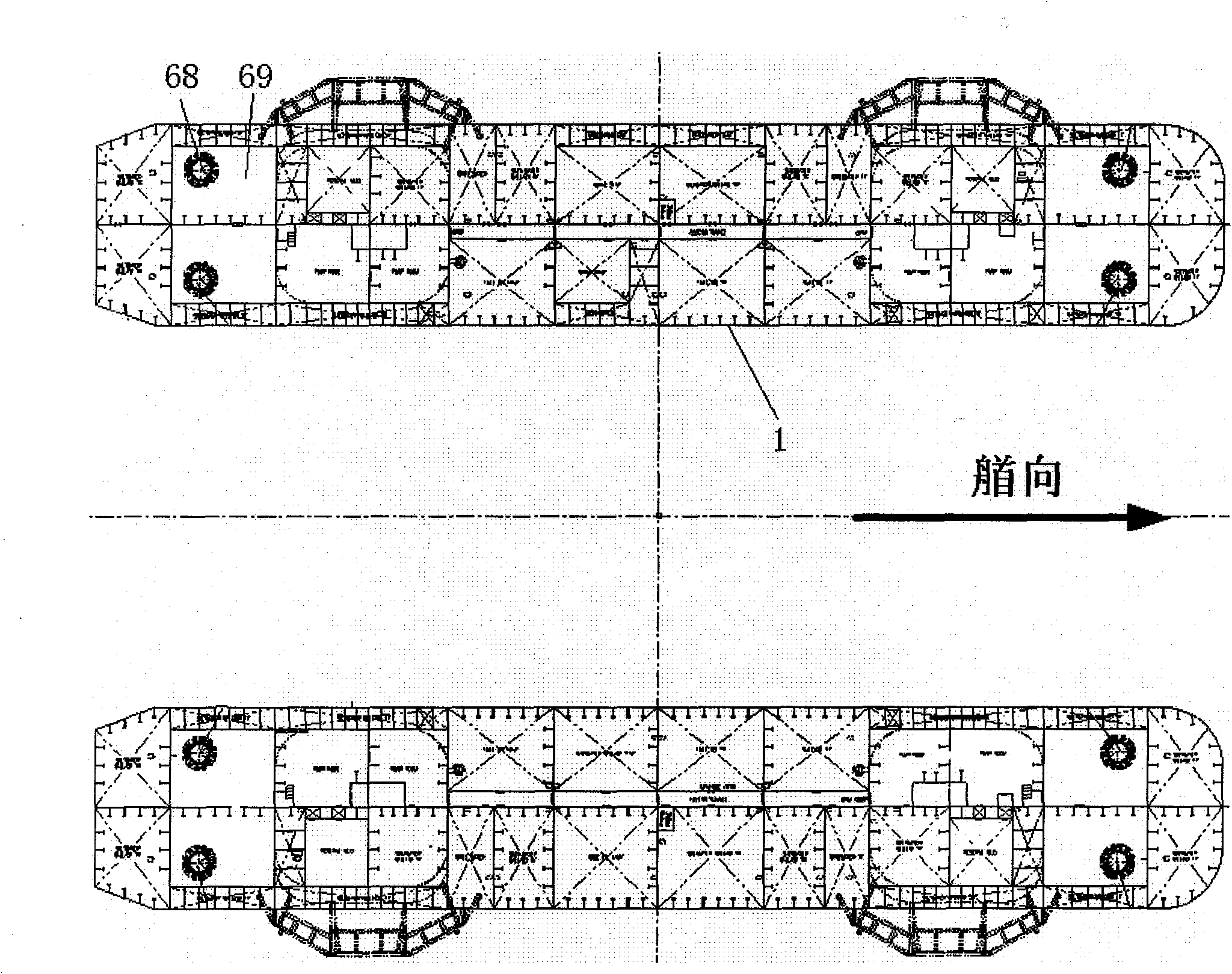
[0046] Such as Figure 1 ~ Figure 3 As shown, the present invention comprises two pontoon tanks 1, each pontoon tank 1 is 114.07m long, 20.12m wide, and 8.54m high, and the center distance between the two pontoon tanks 1 is 59.79m. Two columns 2 are connected to each buoyancy tank 1, and the columns 2 are 17.385m long, 15.860m wide and 21.46m high. The two columns 2 on each pontoon 1 are connected with the two columns 2 on the corresponding pontoon 1 through two sets of cross braces 3, and the top of the four columns 2 supports an upper hull 4, the upper hull 4 is 77.47m long and wide. 74.42m, the top of the upper hull 4 is the main deck 5 .

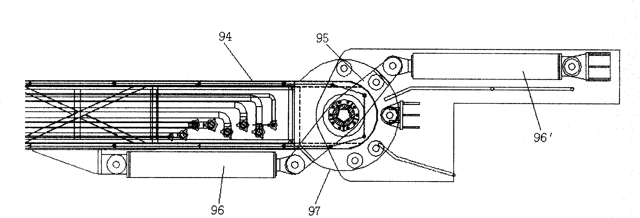
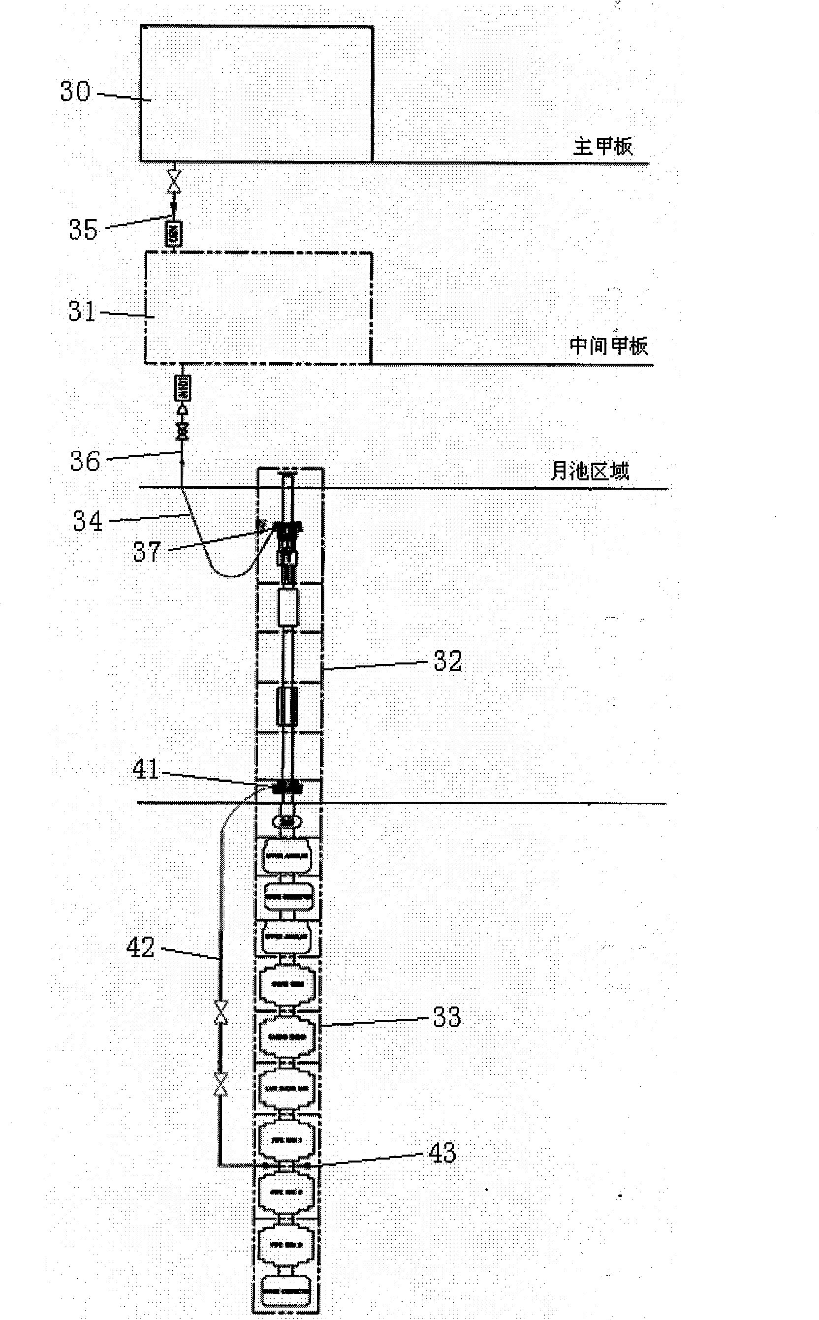
[0047] Such as Figure 1 ~ Figure 4 As shown, the present invention is provided with a drilling system above the moon pool 6 in the middle part of the main deck 5, and the drilling system includes a drilling ...


PUM


Abstract

The invention relates to a deepwater semi-submerged drilling platform, which comprises floating tanks, an upright post, a transverse supporting rod and a main deck, wherein a drilling block is arranged above a moon pool in the middle of the main deck; and a derrick is arranged on the drilling block. The deepwater semi-submerged drilling platform is characterized in that: a half derrick space for pre-connecting a drilling tool is reserved on one side of the derrick; a water isolating pipe, a drilling stem, a blowout preventer and a production tree are arranged on the main deck around the moon pool respectively; and an anchor moored positioning and dynamic positioning combined position system which consists of front and back four groups of anchor gears distributed on the left and right sides of the main deck is adopted, each group of anchor gears are provided with 3 anchor chains, a dynamic positioning system consists of 8 dynamic thrusters capable of rotating 360 degrees at the front and back four corners of the bottom of the two floating tanks. In the deepwater semi-submerged drilling platform, the maximum operation water depth is up to 3,000 meters, the maximum drilling depth is up to 12,000 meters, and the maximum variable load is up to 9,000 tons. The deepwater semi-submerged drilling platform can operate in the South China Sea, Southeast Asian sea area and West Africa sea area with severe sea conditions efficiently and safely.

Description

technical field [0001] The invention relates to a drilling platform, in particular to a deep-water semi-submersible drilling platform which can be used for marine deep-water oil and gas exploration with an operating water depth of up to 3000m. Background technique [0002] The exploration and development of offshore oil and gas resources continue to advance into deep water. The currently used mobile drilling devices mainly include jack-up drilling platforms, drilling ships and semi-submersible drilling platforms. Among them, the jack-up drilling platform cannot carry out the exploration and development of deep-water oil and gas fields due to the limitation of the operating water depth. Compared with the semi-submersible drilling platform, the drilling ship has excellent stability and can adapt to the harsh marine environment. conditions, and work more efficiently. At present, the semi-submersible drilling platform has become the main equipment for drilling and completion op...

Claims


Application Information

Patent Timeline
Patent Type & Authority Applications(China)
IPC IPC(8): B63B35/44
Inventor 林瑶生粟京谢彬傅成玉周守为曾恒一金晓剑刘华祥晏绍枝王浩宇李春璘别顺武李浪清徐鼎基康见逊黄映城周臻栗振宁杨宏滨李东亮赖华山李焱红李亚湖王世圣冯玮
Owner CHINA NAT OFFSHORE OIL CORP
Why Eureka
Try Eureka