
Dynamic positioning of marine vessels

a technology of dynamic positioning and marine vessels, applied in the direction of steering initiation, instruments, vessel construction, etc., can solve the problems of affecting the safety of personnel or equipment, affecting the environment, and the measurement of position in surge and sway has proved to be more complex, so as to eliminate the disadvantages of individual measurements, reliable and stable estimation of vessel position, and fast measurement of motion

Active Publication Date: 2007-10-04
GE POWER CONVERSION
View PDF3 Cites 30 Cited by
  • Summary
  • Abstract
  • Description
  • Claims
  • Application Information

AI Technical Summary

Benefits of technology

[0017]The current invention utilises a measurement of riser bottom angle combined with a measurement of vessel velocity, possibly, but not exclusively, obtained from a Doppler log. These two signals are combined to produce a single position estimate, possibly using a Kalman filter or some other algorithm. The combined position estimate retains the advantages of each of the signals, i.e. the riser bottom angle gives a slow estimate of the vessel required position whilst the velocity measurement gives a fast measurement of motion. This allows the DP system to maintain the position of the vessel within the required limits for long periods in a stable manner.
[0018]Using a riser bottom angle only would result in an unstable control system, since the bottom angle lags the vessel motion by a considerable amount and the relationship is non-linear. Using the velocity measurement alone would result in a slow drift of position. The combination of the two eliminates the disadvantages of the individual measurements.
[0019]For combining the bottom angle and velocity measurements, a Kalman filter is not the only possible algorithm. Any state observer could work, e.g. a Wiener filter or Luenberger observer. One could also theoretically use a simple mixing algorithm using a high-pass filter on the velocities and a low-pass filter on the riser angles.
[0020]The invention allows a reliable and stable estimate of vessel position to be obtained without measuring the top angle of the riser and in particular without the need to model the exact shape of the riser and the profile of currents from sea bed to surface.

Problems solved by technology

In many applications a loss of position beyond the acceptable limits may have a severe impact either on the safety of personnel or equipment, or on the environment.
Whilst the gyrocompass offers a compact, reliable and accurate measurement of vessel heading (yaw), independent of outside disturbances, the measurement of position in surge and sway has proved to be more complex.
No single failure can disable all the taut-wires.
However, for many vessels, taut-wire is not an option; for example, drilling vessels have to operate in increasingly deep water.
In deep water their measurements can be noisy and the interval between measurements increases, leading to loss of positioning accuracy.
Multiple acoustic systems cannot be considered independent of each other since they all rely on the integrity of the same medium—the water.
Deployment and recovery of acoustic beacons are an unavoidable burden on fast turn-around times.
The global positioning system (GPS) and differential GPS (DGPS) now dominate the position measurement market due to their cost, convenience, accuracy and size.
They do, however, share a single mode of failure: ionospheric perturbations, particularly in tropical regions, have resulted in complete loss of GPS measurements for significant periods.
Velocity measurements alone, however, cannot form a permanent position reference due to the drift in position resulting from the integration of errors in the velocity measurements.
However, the disadvantages include the unknown shape of the riser string as it hangs in the water, since it is affected by water currents which can change and which are different at different depths.

Method used


Image

  • Dynamic positioning of marine vessels
  • Dynamic positioning of marine vessels
  • Dynamic positioning of marine vessels

Examples


Embodiment Construction

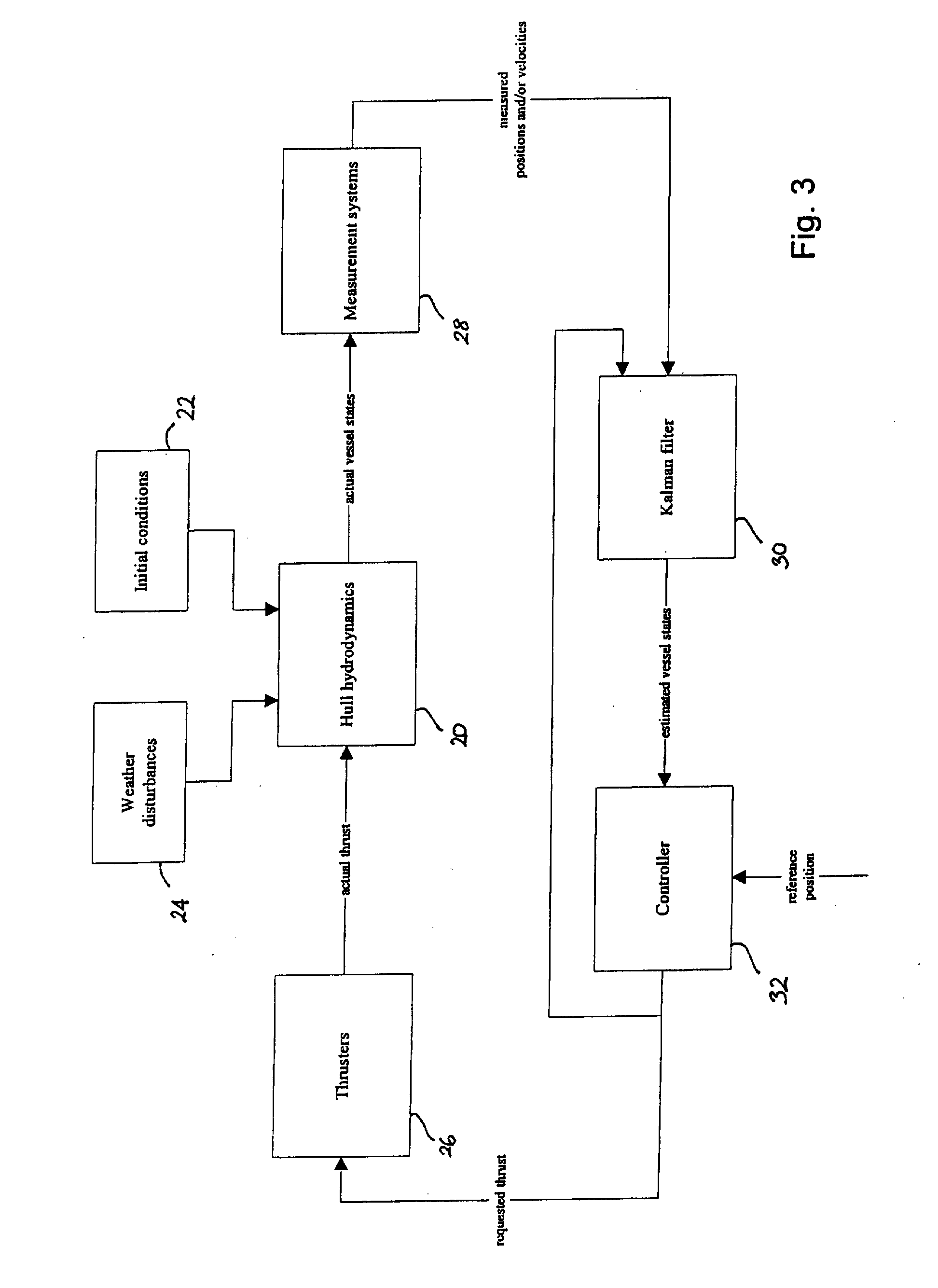
[0025]A preferred embodiment of the invention uses a Kalman filter (KF) to combine measurements of vessel velocity, vessel heading and riser bottom angle with any other position measurements that may be available in order to estimate the vessel's position and heading and dynamically control them.

Basic Kalman Filter Equations

[0026]The basic KF equations (see, for example, {dot over (A)}ström and Wittenmark, Computer Controlled Systems: Theory and Design, 2nd Edition, Prentice-Hall International, Englewood-Cliffs, N.J., USA, 1990) are based on a discrete state space model of the ship as follows:

x(t+τ)=Φx(t)+Γu(t)+w(t)   (1)

y(t)=Hx(t)+v(t)   (2)

where x(t) is the state vector at time t, u is a vector of control inputs and feed-forward forces, y is a vector of measured outputs, τ is the sampling period whilst Φ, Γ and H are matrices defining the transitions of the state vector. w and v are noise processes acting on the states and the output respectively. w and v are assumed to be Gaussia...


PUM


Abstract

Dynamic positioning of a vessel 10 connected to the seafloor 14 by a riser 12 utilises a measurement of riser 12 bottom angle combined with a measurement of vessel 10 velocity, optionally obtained from a Doppler log 16. These two signals are combined to produce a single position estimate using an algorithm such as a Kalman filter. Using riser bottom angle only would result in an unstable control system, since the bottom angle lags the vessel motion by a considerable amount and the relationship is non-linear. Using the velocity measurement alone would result in a slow drift of position. The combination of the two eliminates the disadvantages of the individual measurements.

Description

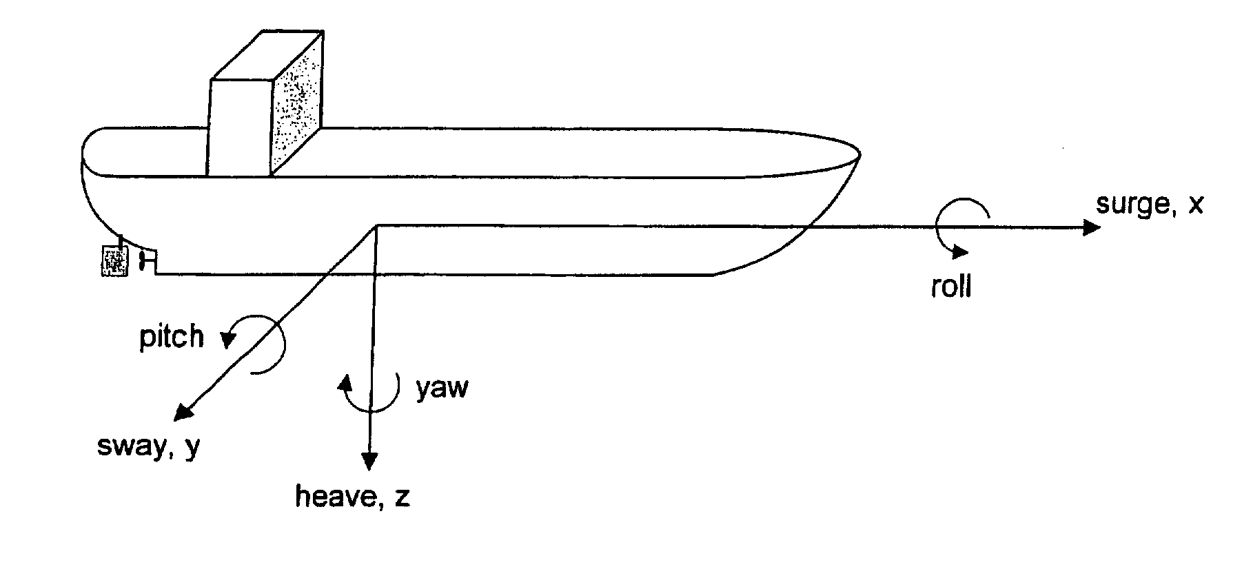
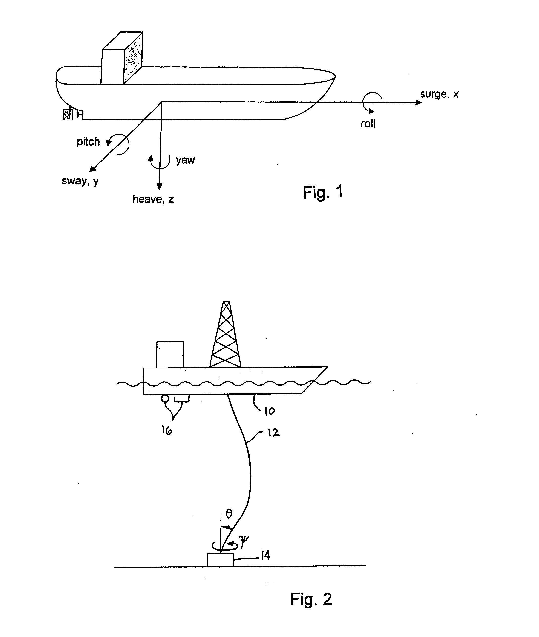
RELATED APPLICATION[0001]This application claims priority under 35 U.S.C. 119 to United Kingdom Application No. 0604205.5, filed Mar. 1, 2006, which application is incorporated herein by reference and made a part hereof.FIELD OF THE INVENTION[0002]The invention relates to the dynamic positioning (DP) of marine vessels, i.e. the use of thrusters to maintain the position of a vessel in the vicinity of a reference point and stabilise its heading, in opposition to environmental forces such as wind and current.[0003]The term “vessels” is intended to include ships, drilling rigs and any other surface-going vessels or platforms. The invention is principally relevant to applications in deep water but the use herein of the word “marine” is not intended to exclude its application in freshwater lakes.BACKGROUND OF THE INVENTION[0004]A ship moves in six axes, three translational (surge, sway and heave) and three rotational (roll, pitch and yaw). These six axes are shown in FIG. 1. A DP system f...

Claims


Application Information

Patent Timeline
Patent Type & Authority Applications(United States)
IPC IPC(8): G01V1/40
CPCB63B21/50B63H25/00G05D1/0206B63H25/42B63H25/04G05D1/0208G01C21/203G01S11/14
Inventor STEPHENS, RICHARD IAN
Owner GE POWER CONVERSION
Learn More