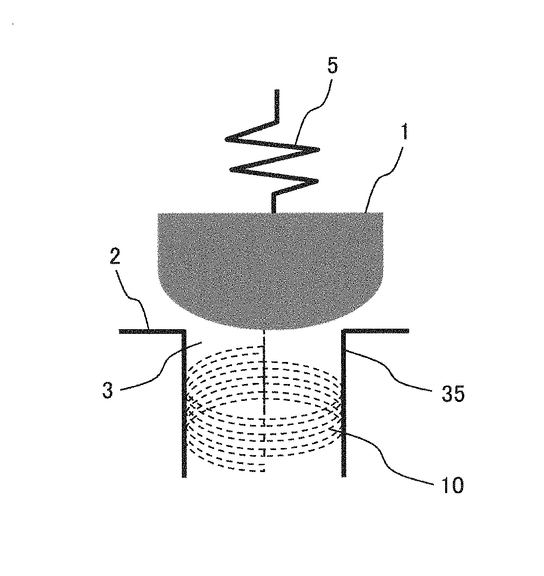
Valve structure, and hydraulic device, fluid machine, and machine, each having same
a valve and hydraulic device technology, applied in the direction of valve housings, fluid dynamics, functional valve types, etc., can solve the problems of insufficient effect and prone to vibration of the above valve type, and achieve the effect of suppressing the vibration phenomenon of the valve, suppressing the amount of vortex generation, and suppressing the fluctuation of fluid for
- Summary
- Abstract
- Description
- Claims
- Application Information
AI Technical Summary
Benefits of technology
Problems solved by technology
Method used
Image
Examples
first embodiment
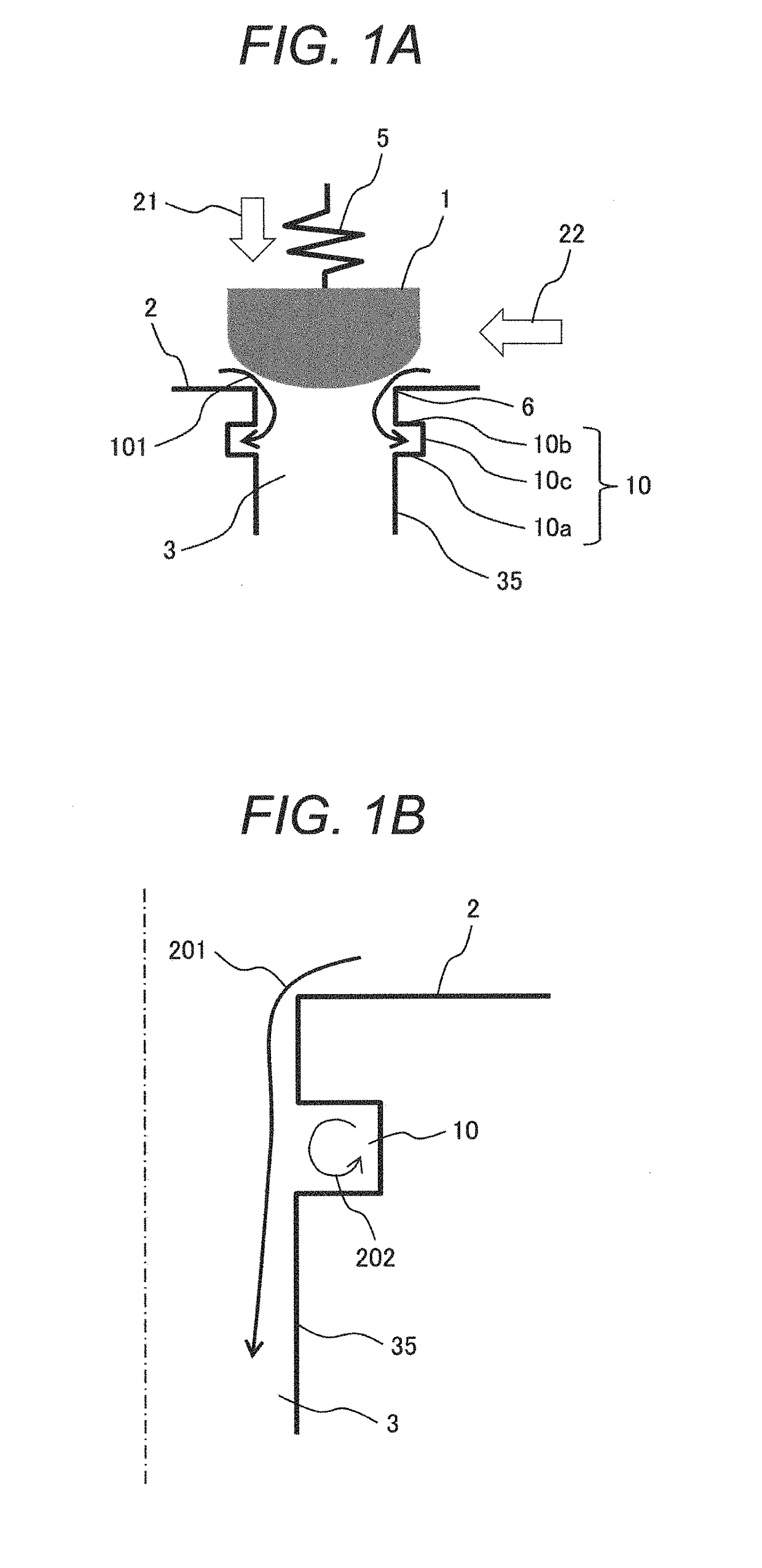
[0023]FIG. 1A is a schematic longitudinal cross-sectional view illustrating a valve structure according to a first embodiment.
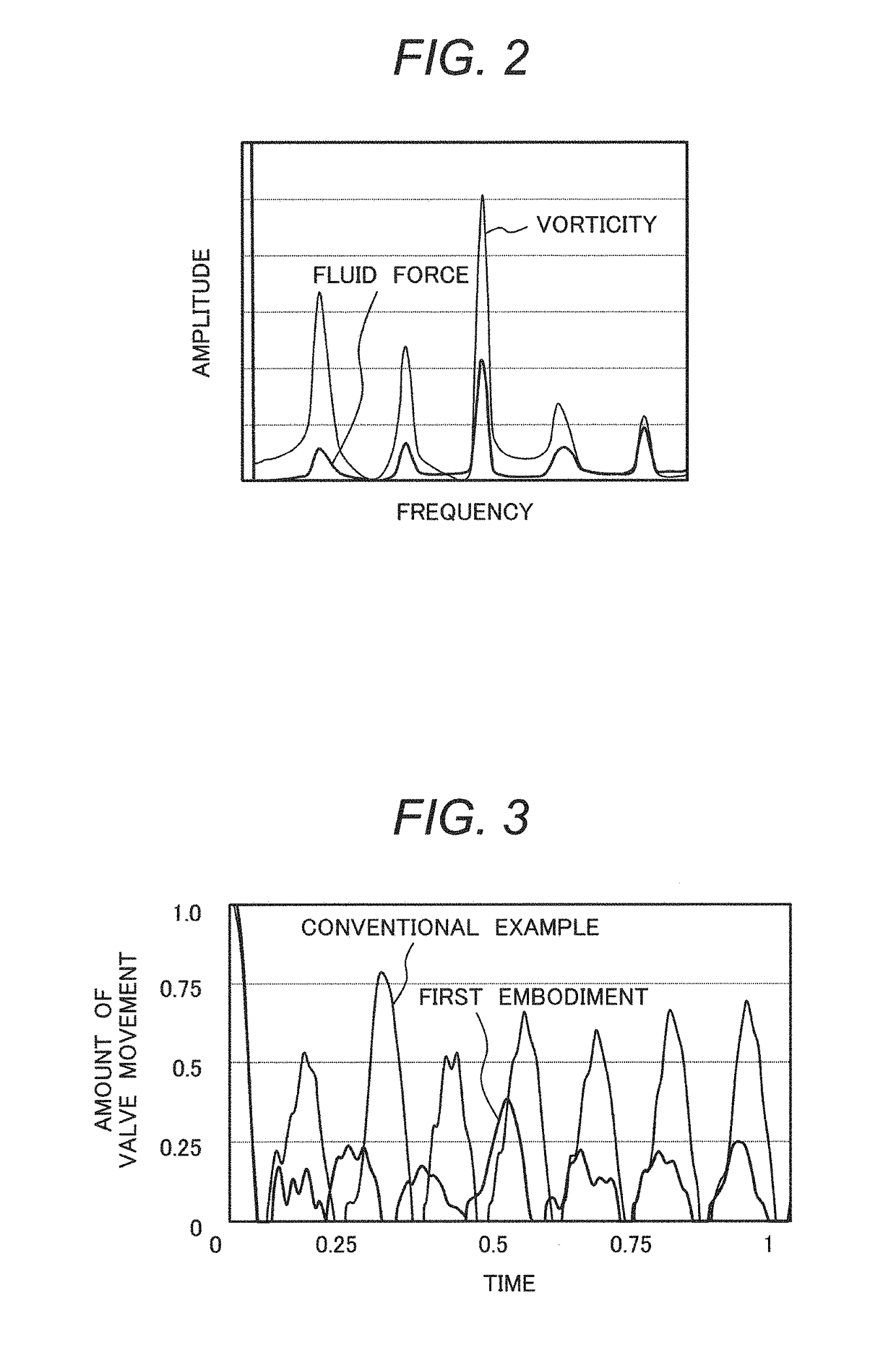
[0024]Referring to FIG. 1A, essential elements of the valve structure are a valve body 1, a valve seat 2, and a spring 5. The valve seat 2 includes a flow path 3. While a valve is closed, the valve body 1 and the valve seat 2 are in contact with each other at a contact section 6. FIG. 1A shows a state where the valve is open. A groove 10 is formed along the entire periphery of a flow path wall 35 downstream of the contact section 6. In the first embodiment, the flow path 3 is shaped like a circular hole when viewed cross-sectionally, and the groove 10 is annular in shape. The cross-sectional shape of the groove 10 is rectangular as viewed in FIG. 1A. The wall surface of the groove 10 is formed of a lower groove surface 10a, an upper groove surface 10b, and a lateral groove surface 10c. A flow line 101 depicts a fluid that flows into the groove 10 through the ...
second embodiment
[0039]FIG. 4 illustrates the valve structure according to a second embodiment.
[0040]The second embodiment has the same basic configuration as the first embodiment. The second embodiment differs from the first embodiment in that two or more grooves 10 are formed along the entire periphery of the flow path wall 35 downstream of the contact section 6.
[0041]As the above-described structure is employed, a vortex unprocessable by an upstream groove 10 can be guided to a downstream groove 10.
third embodiment
[0042]FIG. 5 illustrates the valve structure according to a third embodiment.
[0043]The third embodiment has the same basic configuration as the first embodiment. The third embodiment differs from the first embodiment in that a spiral groove 10 is formed along the entire periphery of the flow path wall 35 downstream of the contact section 6.
[0044]In FIG. 5, the groove 10 in the flow path wall 35 is deformed in a partial perspective view in order to clearly indicate that the groove 10 is spirally formed.
[0045]The above-described spiral groove 10 acts on a fluid in the same manner as in the first and second embodiments, guides a vortex into the groove 10, and suppresses the occurrence of vortex-induced vibration.
[0046]The spiral structure of the groove 10 according to the present invention is preferably parallel to a plane orthogonal to the central axis of the flow path. Alternatively, however, the spiral structure of the groove 10 may be at a predetermined angle from such a plane. The...
PUM
 Abstract
Description
Claims
Application Information
 - R&D
- Intellectual Property
- Life Sciences
- Materials
- Tech Scout
- Unparalleled Data Quality
- Higher Quality Content
- 60% Fewer Hallucinations
Browse by: Latest US Patents, China's latest patents, Technical Efficacy Thesaurus, Application Domain, Technology Topic, Popular Technical Reports.
© 2025 PatSnap. All rights reserved.Legal|Privacy policy|Modern Slavery Act Transparency Statement|Sitemap|About US| Contact US: help@patsnap.com


