Vehicular antenna device
a technology of antenna device and antenna, which is applied in the direction of resonant antenna, antenna earthing, television system, etc., can solve the problems of radio reception trouble, tv reception trouble, and noise radiated from the module cable, so as to prevent reception trouble and suppress electromagnetic nois
- Summary
- Abstract
- Description
- Claims
- Application Information
AI Technical Summary
Benefits of technology
Problems solved by technology
Method used
Image

Examples
embodiment 1
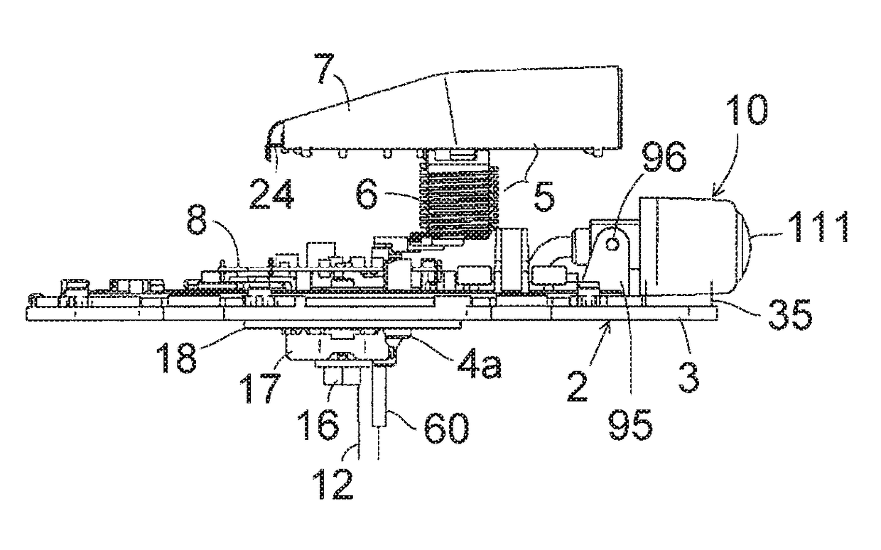
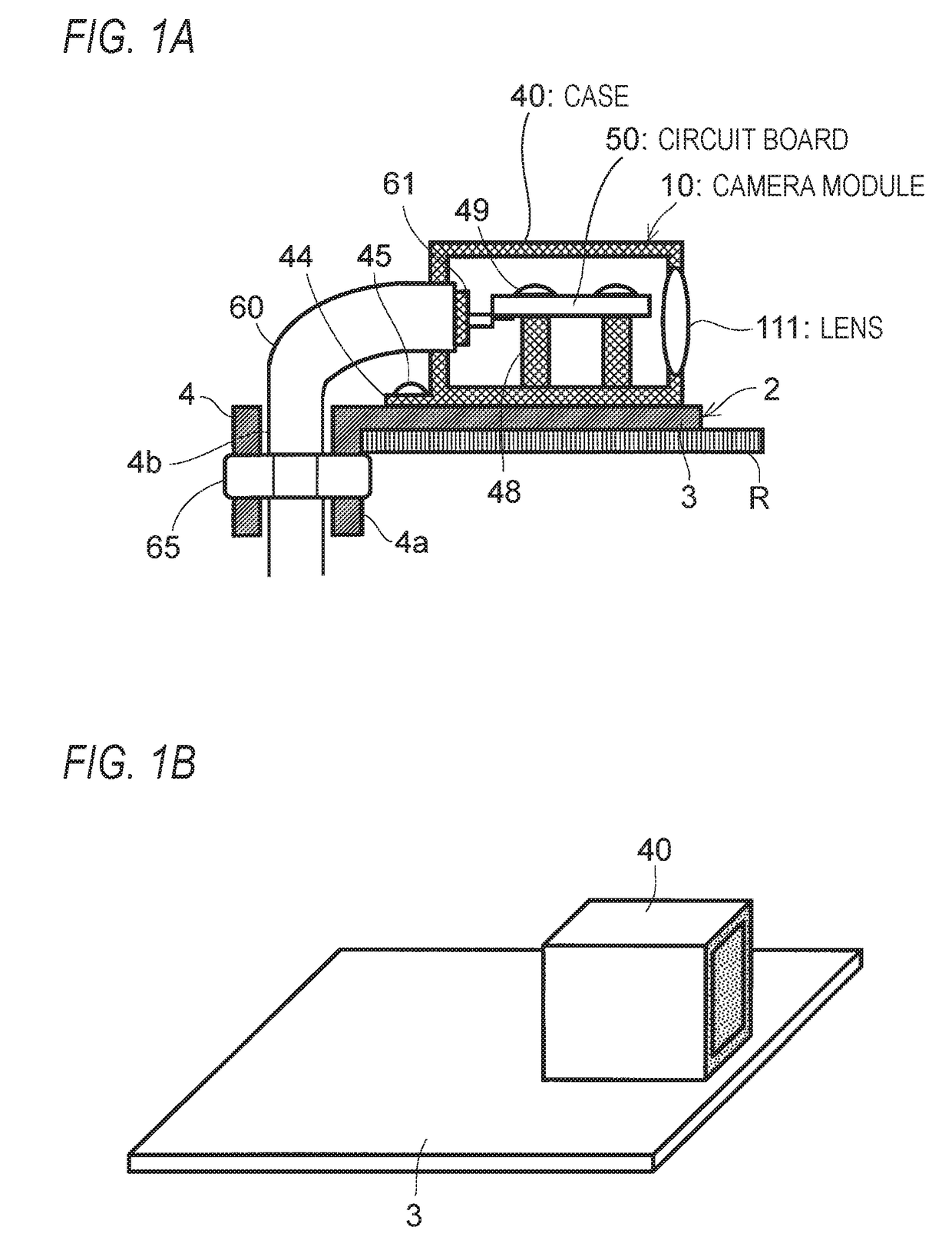
[0078]FIG. 1A shows the configuration of an essential part of the vehicular antenna device according to the first embodiment of the present invention, and shows a noise reduction shield structure of the vehicular antenna device 1 shown in FIGS. 5-10. In this case, a camera module case 40 of the camera module 10 is a metal member (e.g., aluminum diecast member) that also serves as a shield conductor for shielding a circuit board 50 by surrounding it. The lens 111 is attached to a rear wall of the camera module case 40, and the circuit board 50 is fixed to bosses (projections) 48 which project inside the case 40 by metal board attachment screws 49. The circuit board 50 which is housed in the case 40 is mounted with an image sensor unit 112, a video signal output unit 113, an oscillator 114, a power unit 115 for supplying electric power to the circuit units, a noise filter 130, etc. which are shown in FIG. 17 (the structure, workings, and advantages of the noise filter 130 will be desc...
embodiment 2
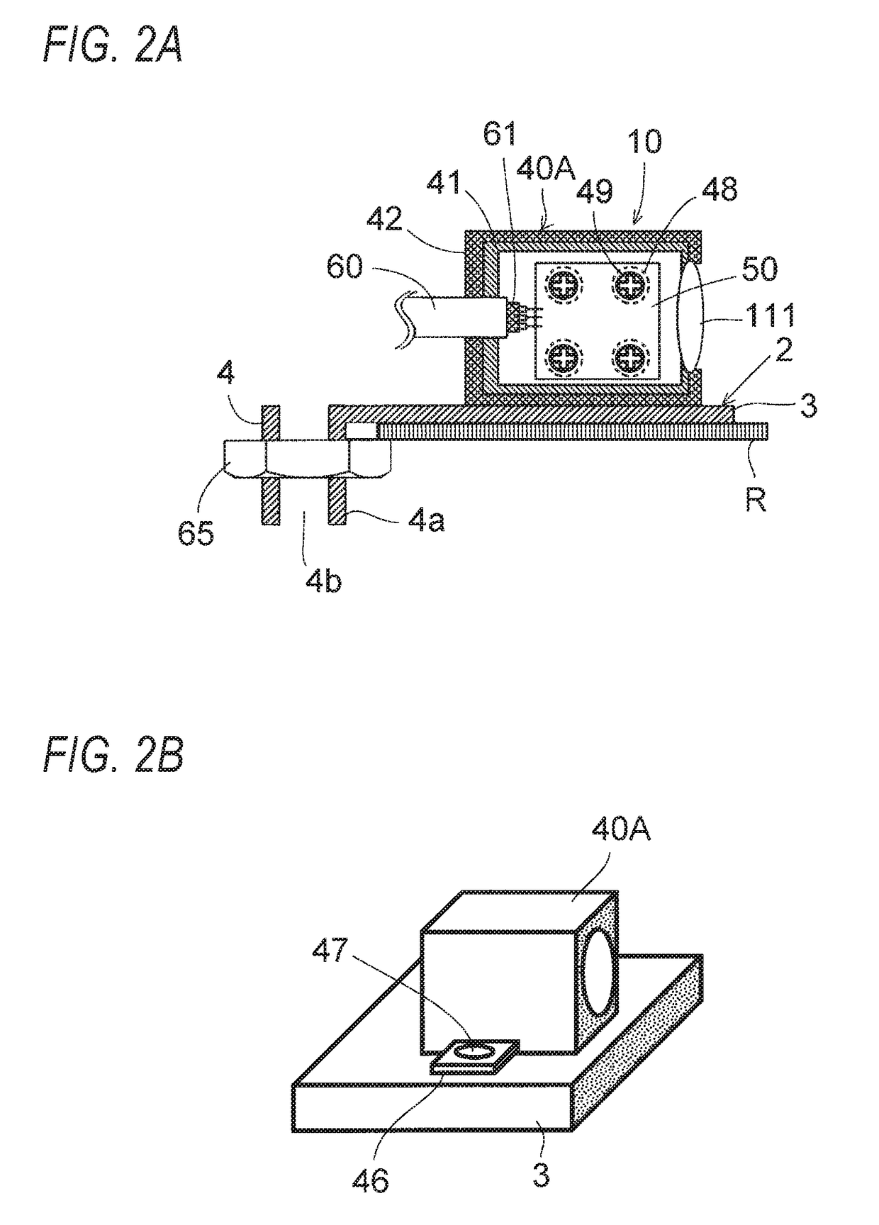
[0099]FIG. 2A shows the configuration of an essential part of the vehicular antenna device according to the second embodiment of the present invention, and shows a noise reduction shield structure of the antenna device 1 shown in FIGS. 5-10. In this case, a camera module case 40A of the camera module 10 is such that a shield conductor 42 is formed on the entire outer surfaces of an insulative body 41 (synthetic resin mold) by coating or plating of a conductive material or a like method. The camera module 10 is disposed on the metal baseplate 3. A circuit board 50 of the camera module 10 is fixed to bosses 48 which project inside the case 40A by board attachment screws 49. Since the case 40A of the camera module 10 is such that the shield conductor 42 is formed on the entire outer surfaces of the insulative body 41 by coating or plating of a conductive material or a like method, as shown in FIG. 2B the case 40A is fixed to and electrically connected to the antenna base 2 at the same ...
embodiment 3
[0101]FIG. 3A shows the configuration of an essential part of the vehicular antenna device according to the third embodiment of the present invention, and shows a noise reduction shield structure of the antenna device 1 shown in FIGS. 5-10. In this case, the camera module 10 is disposed on the metal baseplate 3 and a camera module case 40B of the camera module 10 is such that a shield conductor 43 is formed on the entire inner surfaces of an insulative body 41 excluding a lens portion by coating or plating of a conductive material or a like method. One end portion of the shield sheath conductor 61 of the module cable 60 connected to a circuit board 50 is electrically connected to the shield conductor 43 by soldering or the like and its other end portion is grounded to the vehicle body roof R via a connecting member 80 shown in FIG. 3B. More specifically, the connecting member 80 is a member in which a tubular terminal 82 and a washer-like terminal 83 are connected to the two respect...
PUM
 Abstract
Description
Claims
Application Information
 - R&D
- Intellectual Property
- Life Sciences
- Materials
- Tech Scout
- Unparalleled Data Quality
- Higher Quality Content
- 60% Fewer Hallucinations
Browse by: Latest US Patents, China's latest patents, Technical Efficacy Thesaurus, Application Domain, Technology Topic, Popular Technical Reports.
© 2025 PatSnap. All rights reserved.Legal|Privacy policy|Modern Slavery Act Transparency Statement|Sitemap|About US| Contact US: help@patsnap.com