Power factor correction conversion device and control method thereof

a conversion device and power factor technology, applied in the direction of dc-dc conversion, energy industry, efficient power electronics conversion, etc., can solve the problems of system reducing power factor, power transmission may suffer loss, system manifesting slower transient response to load change, etc., to increase the response speed of a pfc voltage loop, and reduce the distortion rate of input current.

Active Publication Date: 2017-08-15
NAT CHUNG SHAN INST SCI & TECH
View PDF9 Cites 4 Cited by
  • Summary
  • Abstract
  • Description
  • Claims
  • Application Information

AI Technical Summary

Benefits of technology

[0004]It is an objective of the present invention to increase the response speed of a PFC voltage loop while keeping a low distortion rate of the input current, so as to increase the power factor sent to a back-end load.
[0005]Another objective of the present invention is to reduce the DC-link capacitance generated from PFC circuit output to thereby reduce costs.
[0015]In an embodiment of the present invention, the power factor correction conversion device further comprises an electromagnetic interference filter adapted to receive the AC input signal and coupled to the rectification circuit to suppress electromagnetic noise of the AC input signal.
[0017]Hence, the present invention is characterized in that: a second-order ripple component is eliminated from a feedback signal so as to increase the response speed of a power factor correction conversion device and reduce the distortion rate of the current, thereby increasing a power factor sent to a back-end load. Furthermore, the present invention reduces the DC-link capacitance generated from a PFC circuit to thereby reduce costs.

Problems solved by technology

When the power factor is less than 1, the power transmitted may suffer a loss because of phase mismatch between the current and voltage or the introduction of noise.
However, the current distortion of the aforesaid circuit is large and contains plenty of harmonic components, thereby reducing the power factor.
However, the method has a drawback, that is, the system manifests slower transient response to a change of the load.
As a result, persons skilled in the art are in a dilemma between a slow transient response from the system and a distorted waveform of the input current.

Method used


Image

  • Power factor correction conversion device and control method thereof
  • Power factor correction conversion device and control method thereof
  • Power factor correction conversion device and control method thereof

Examples


Embodiment Construction

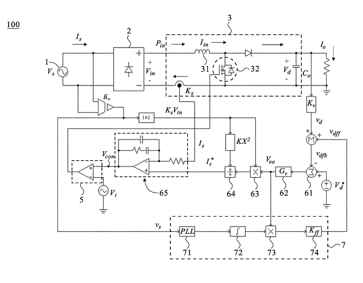
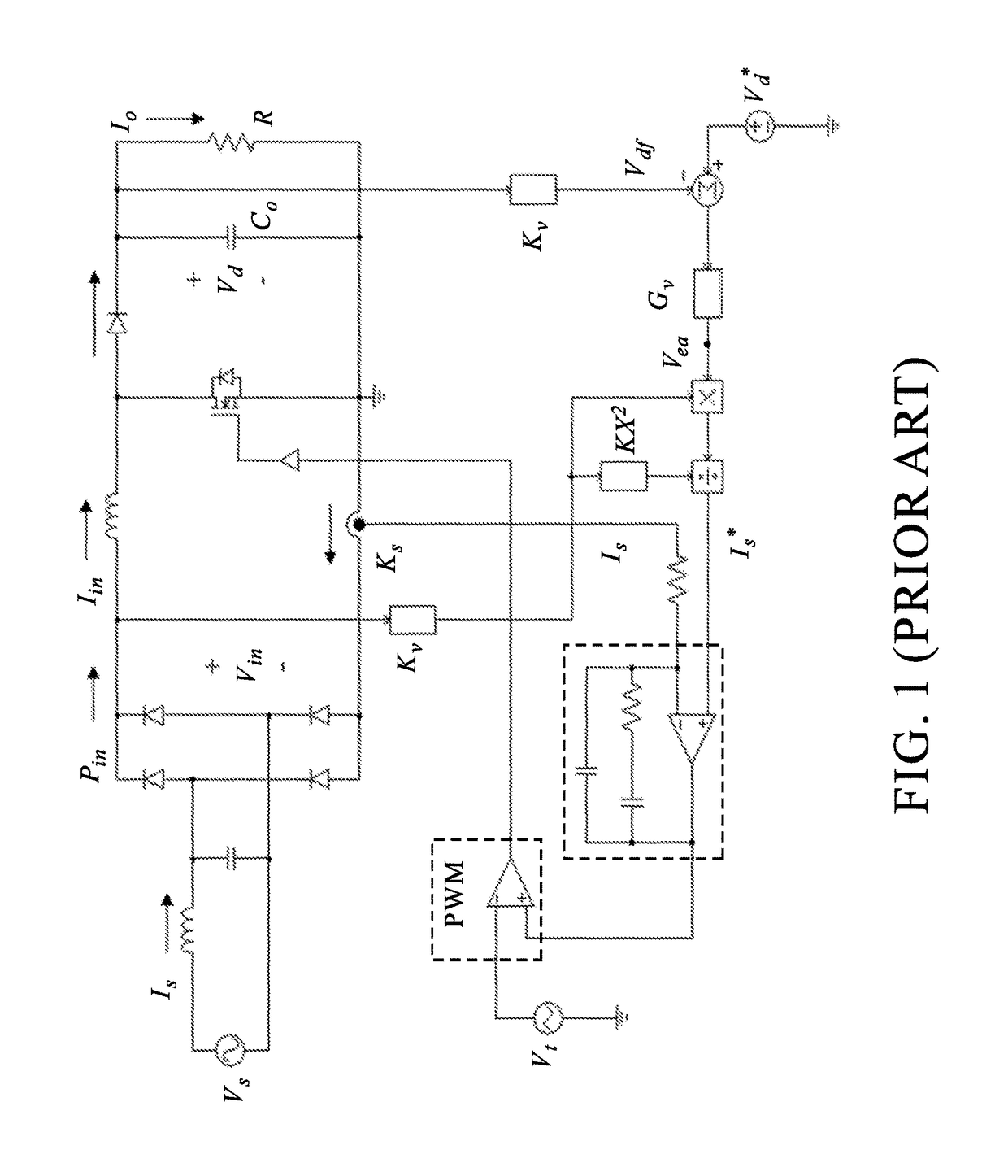
[0026]FIG. 1 is a circuit diagram of a conventional power factor correction (PFC) conversion device. FIG. 5 is a circuit diagram of the power factor correction conversion device in an embodiment of the present invention. Referring to FIG. 1 and FIG. 5, in the embodiments of the present invention, a ripple calculation circuit 7 is introduced into the conventional power factor correction conversion device to provide the power factor correction conversion device of the present invention with a view to eliminating the second-order ripple component of a feedback DC-link voltage.

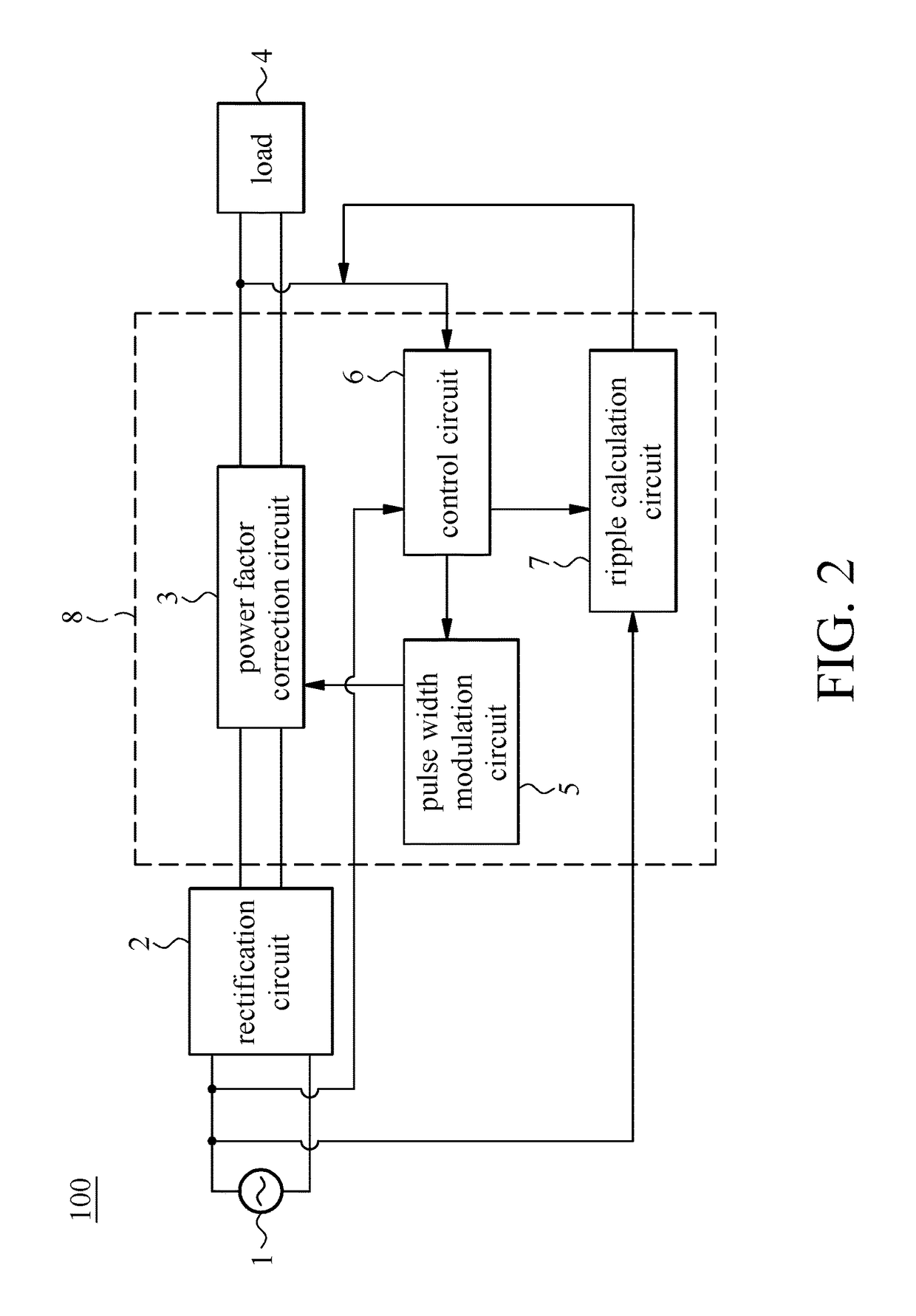
[0027]In an embodiment, the present invention provides a power factor correction conversion device 100. Referring to FIG. 2 and FIG. 5, the power factor correction conversion device comprises a rectification circuit 2 and a power factor correction module 8. The rectification circuit 2 receives an AC input signal 1 and rectifies the AC input signal 1, so as to generate a DC signal. The power factor correction modul...


PUM


Abstract

A power factor correction conversion device and control method thereof are adapted to send an AC signal to a power factor correction conversion device, convert the AC signal into a DC signal, and perform power factor correction of the DC signal, so as to change a power factor sent to a back-end load, wherein the control method includes a rectification step, a feedback step, a ripple calculating step, a ripple offsetting step, a logical computation step, a pulse width modulation step and a power factor correcting step. Hence, the second-order ripple component in a feedback signal is eliminated to thereby increase the response speed of the power factor correction conversion device and reduce the distortion rate of the current, thus increasing the power factor sent to the back-end load.

Description

FIELD OF TECHNOLOGY[0001]The present invention relates to power conversion devices and control methods thereof and more particularly to a power factor correction conversion device and a control method thereof.BACKGROUND[0002]A load exhibits resistive impedance, inductive impedance, capacitive impedance or a combination thereof toward a power supply device. The power factor approaches 1, when the current input to the load is in phase with the voltage applied to the load. When the power factor is less than 1, the power transmitted may suffer a loss because of phase mismatch between the current and voltage or the introduction of noise. According to the prior art, to convert an AC power of a utility grid into a DC voltage, large-capacity capacitors are connected in parallel to reduce the second-order ripple component of a DC-link (DC bus) voltage and thus provide a stable DC-link voltage to a succeeding voltage transformer. However, the current distortion of the aforesaid circuit is lar...

Claims


Application Information

Patent Timeline
Patent Type & Authority Patents(United States)
IPC IPC(8): H02M1/42H02M1/14H02M7/04H02M1/00
CPCH02M1/4225H02M1/143H02M1/42H02M7/04H02M2001/0022H02M2001/0025Y02B70/10Y02P80/10H02M1/0022H02M1/0025H02M3/1566
Inventor WU, CHI-SHENGYOU, GWO-HUEICHIANG, HSUANG-CHANGTAI, TSANG-LI
Owner NAT CHUNG SHAN INST SCI & TECH
Why Eureka
Try Eureka