
Driving method and driving circuit for piezoelectric transformer, cold-cathode tube light-emitting apparatus, liquid crystal panel and device with built-in liquid crystal panel

a driving circuit and cold cathode tube technology, applied in the direction of piezoelectric/electrostrictive device details, instruments, device details, etc., can solve the problems of difficult enhancement of conversion efficiency, decreased efficiency, and decreased efficiency of inverter circuits, so as to enhance the driving efficiency of piezoelectric transformers and suppress electromagnetic noise.

Inactive Publication Date: 2005-06-28
PANASONIC CORP
View PDF15 Cites 4 Cited by
  • Summary
  • Abstract
  • Description
  • Claims
  • Application Information

AI Technical Summary

Benefits of technology

[0020]Therefore, with the foregoing in mind, it is an object of the present invention to provide a driving method and a driving circuit for a piezoelectric transformer, in which the value of an input current of a harmonic component other than a driving frequency included in a driving signal of a piezoelectric transformer is suppressed without using an inductive element, whereby a driving efficiency of the piezoelectric transformer is enhanced, and electromagnetic noise is suppressed.
[0021]It is another object of the present invention to provide a driving method and a driving circuit for a piezoelectric transformer in which reliability is enhanced in terms of withstand power and distortion by suppressing a higher order vibration mode excited by a harmonic component other than a driving frequency, included in a driving signal of the piezoelectric transformer.
[0044]According to the first to third driving methods and driving circuits of a piezoelectric transformer, by suppressing an input current value of a harmonic component other than a driving frequency, included in the driving signal of the piezoelectric transformer, without using an inductive element, the driving efficiency of the piezoelectric transformer can be enhanced, and electromagnetic noise can be suppressed.
[0045]According to the fourth to sixth driving methods and driving circuits of a piezoelectric transformer, by suppressing a higher order vibration mode excited by a harmonic component other than a driving frequency, included in the driving signal of the piezoelectric transformer, without using an inductive element, the reliability of the piezoelectric transformer due to withstand power and distortion can be enhanced.
[0046]By including a cold-cathode tube light-emitting apparatus for controlling the light emission of a cold-cathode tube by the above-mentioned driving circuit of the piezoelectric transformer in a liquid crystal panel, and incorporating the liquid crystal panel in a device such as a mobile telephone and a communication terminal, the device can be miniaturized, and its reliability can be enhanced.

Problems solved by technology

As a result, the efficiency of the inverter circuit decreases and the efficiency decreases due to the influence of a dielectric loss in the piezoelectric transformer, which makes it difficult to enhance a conversion efficiency.
Furthermore, when a high-order vibration mode of the piezoelectric transformer is excited with a harmonic component, distortion due to a high-order vibration mode superimposed on a desired vibration mode may be generated in the piezoelectric transformer.
This causes a decrease in the withstand power of the piezoelectric transformer, and degradation of the characteristics due to a large amplitude operation, leading to a decrease in reliability.
The above-mentioned problem becomes an obstacle to the miniaturization of a piezoelectric inverter, and the miniaturization of communication equipment using a liquid crystal panel in which a light-emitting apparatus of a cold-cathode tube is built, using a piezoelectric inverter.

Method used


Image

  • Driving method and driving circuit for piezoelectric transformer, cold-cathode tube light-emitting apparatus, liquid crystal panel and device with built-in liquid crystal panel
  • Driving method and driving circuit for piezoelectric transformer, cold-cathode tube light-emitting apparatus, liquid crystal panel and device with built-in liquid crystal panel
  • Driving method and driving circuit for piezoelectric transformer, cold-cathode tube light-emitting apparatus, liquid crystal panel and device with built-in liquid crystal panel

Examples


embodiment 1

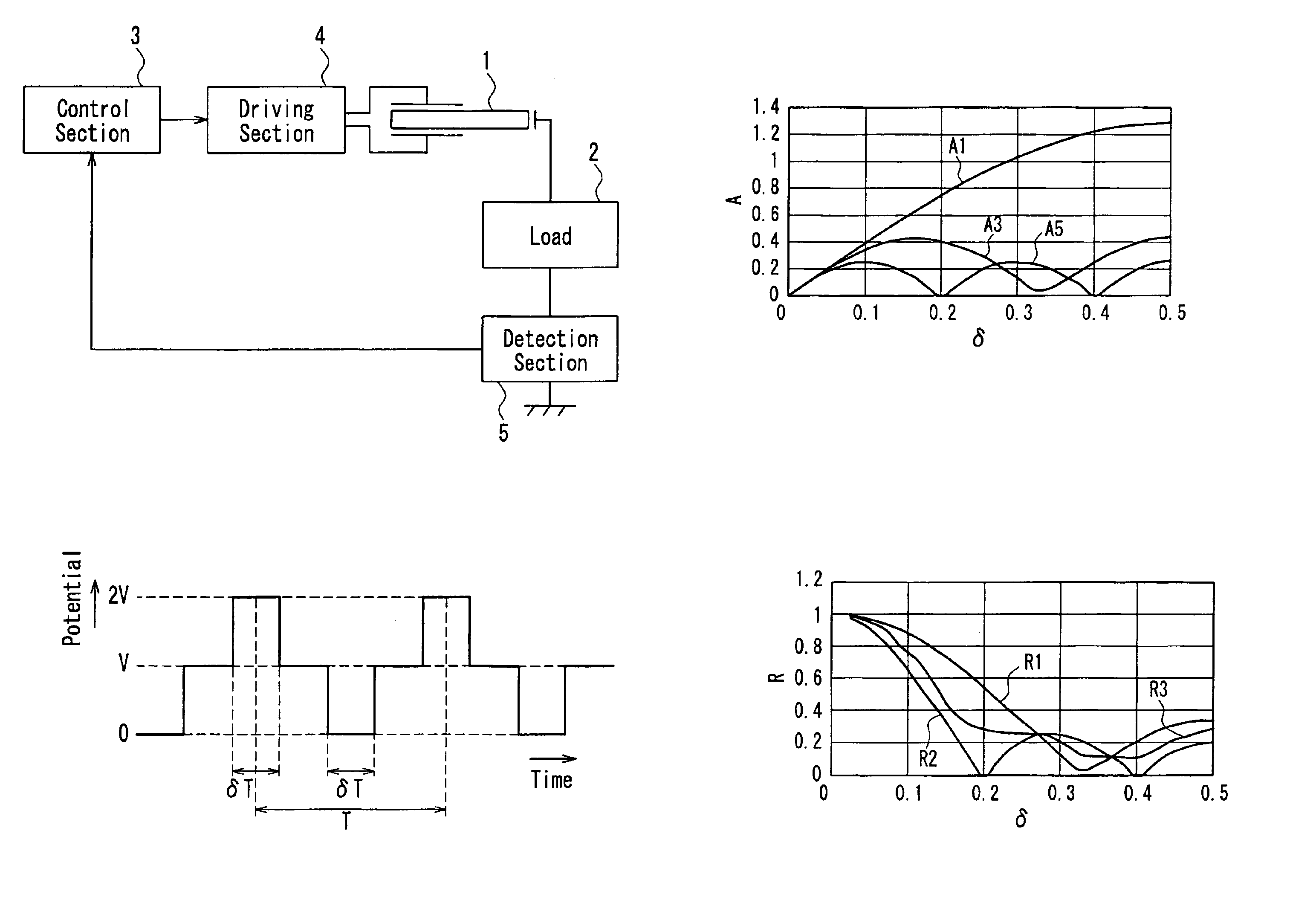
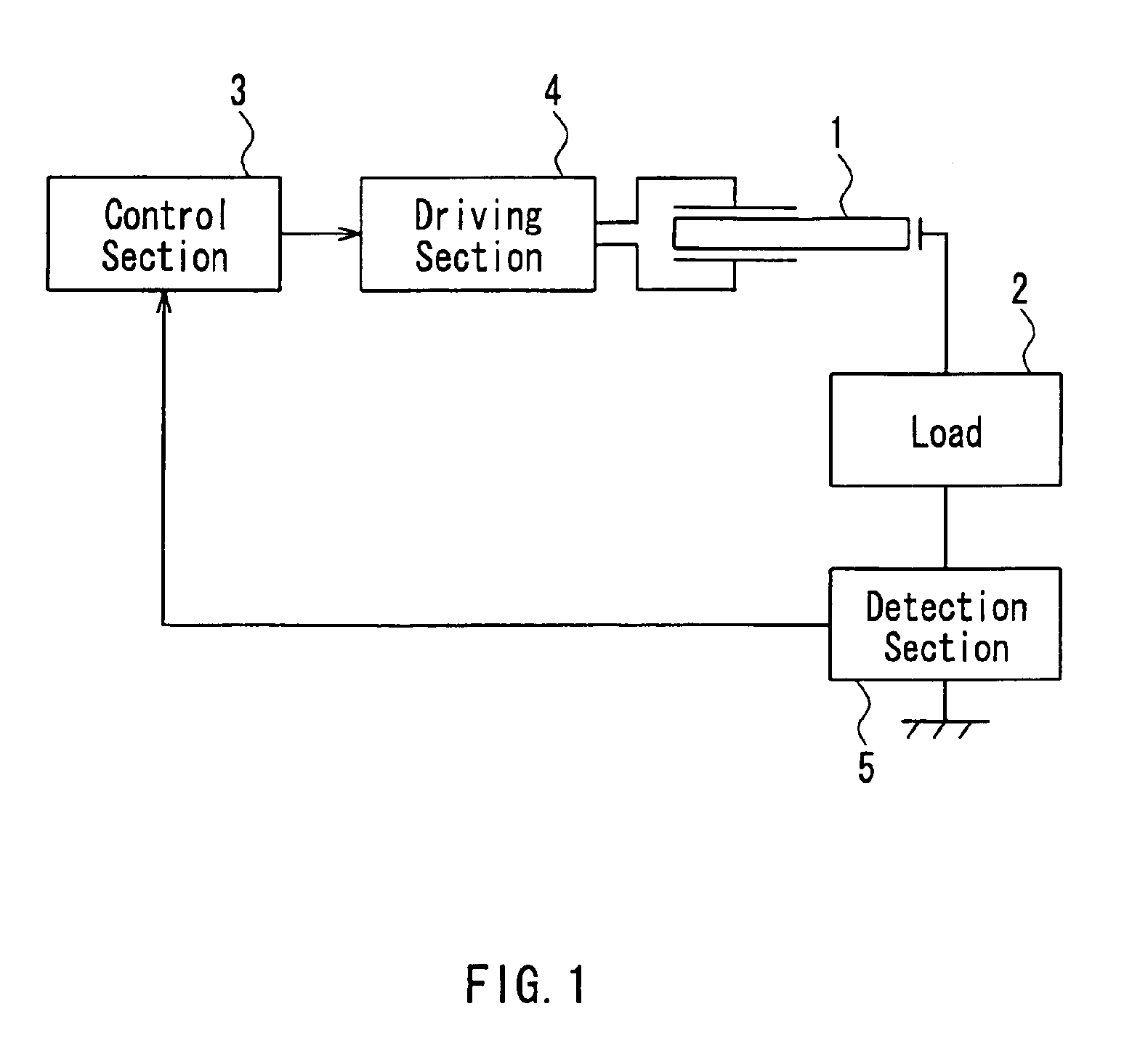
[0072]FIG. 1 is a block diagram showing an exemplary configuration of a driving circuit for a piezoelectric transformer according to Embodiment 1 of the present invention. In FIG. 1, reference numeral 1 denotes a piezoelectric transformer, 2 denotes a load, 3 denotes a control section, 4 denotes a driving section, and 5 denotes a detection section.

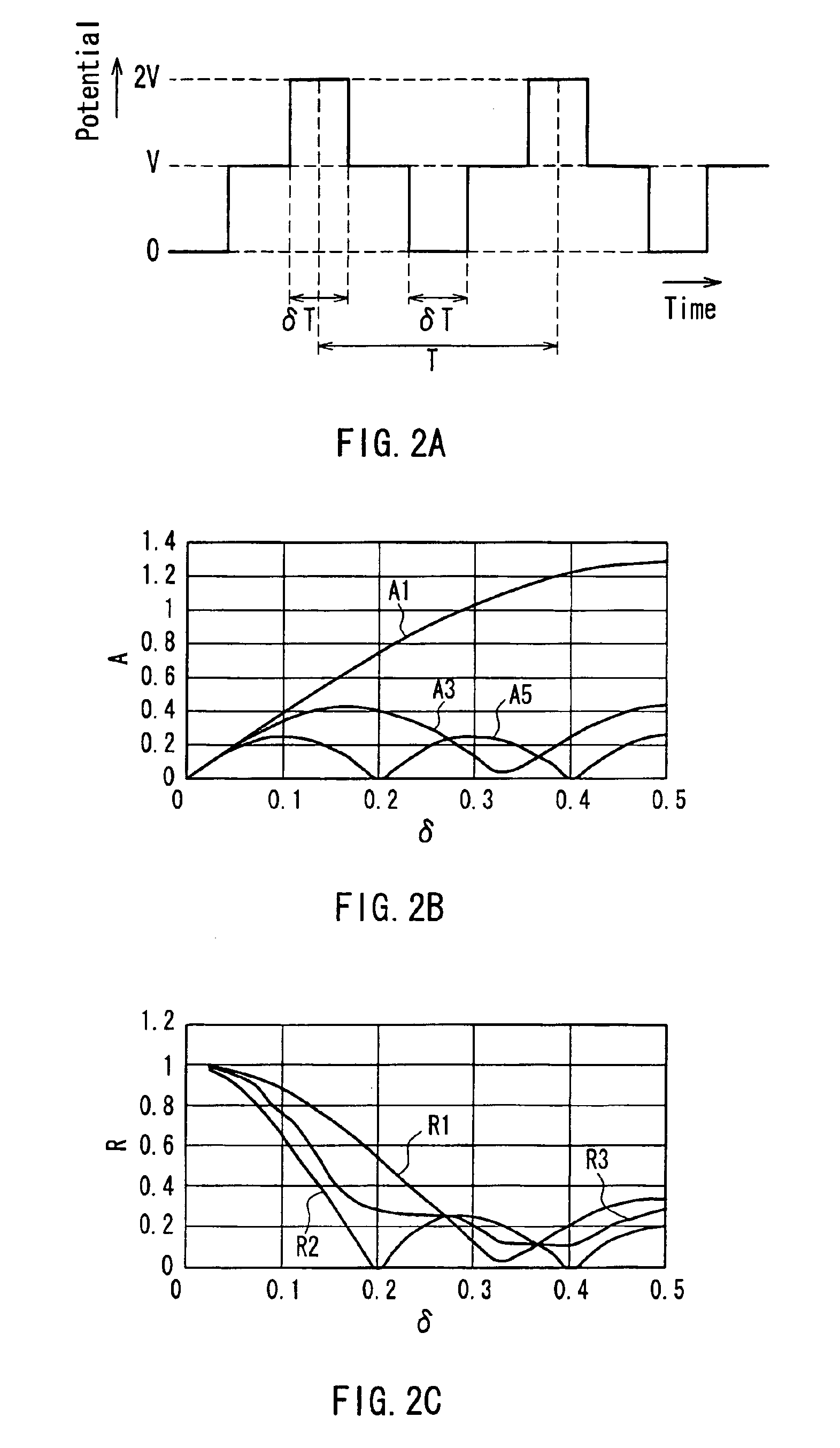
[0073]FIG. 2A is a waveform diagram showing an example of a driving signal in a rectangular waveform applied from the driving section 4 to the piezoelectric transformer 1. In FIG. 2A, a period T of the driving signal in a rectangular waveform corresponds to a reciprocal of a driving frequency of the piezoelectric transformer 1, and a time period in which the potential of the driving signal is a maximum potential (2V) or a minimum potential (0) is set to be δT. V denotes an intermediate potential. More specifically, δ represents a time ratio at which the level of the driving signal is a maximum potential or a minimum potential, with respect...

embodiment 2

[0085]FIG. 3 is a block diagram showing an exemplary configuration of a driving circuit for a piezoelectric transformer according to Embodiment 2 of the present invention. In FIG. 3, the components having the same configurations and functions as those in Embodiment 1 shown in FIG. 1 are denoted with the same reference numerals as those therein, and the description thereof will be omitted here.

[0086]In FIG. 3, a driving section 14 has a configuration in which a first switching element 16, a second switching element 17, a resistor R1, and a resistor R2 are connected in series to each other. One primary side electrode of the piezoelectric transformer 1 is grounded. A gate of the first switching element 16 is supplied with a first control signal S1 from a control section 13, and a gate of the second switching element 17 is supplied with a second control signal S2 from the control section 13. A driving signal S3 is output from a common connection portion of the resistors R1 and R2.

[0087]...

embodiment 3

[0095]FIG. 7 is a block diagram showing an exemplary configuration of a driving circuit for a piezoelectric transformer according to Embodiment 3 of the present invention. In FIG. 7, the components having the same configurations and functions as those in Embodiment 1 shown in FIG. 1 are denoted with the same reference numerals as those therein, and the description thereof will be omitted here.

[0096]In FIG. 7, a driving section 24 is composed of a first series connection body in which a first switching element 26 and a second switching element 27 are connected in series, and a second series connection body in which a third switching element 28 and a fourth switching element 29 are connected in series. A common connection portion (an output portion of the first series connection body) between the first switching element 26 and the second switching element 27 is connected to one primary side electrode of the piezoelectric transformer 1. A common connection portion (an output portion of...


PUM

PropertyMeasurementUnit
driving frequencyaaaaaaaaaa
frequencyaaaaaaaaaa
timeaaaaaaaaaa

Abstract

There is provided a method for driving a piezoelectric transformer in which a driving efficiency and the reliability in terms of withstand power and distortion can be enhanced by suppressing a higher order vibration mode exited by a harmonic component other than a driving frequency included in a driving signal of the piezoelectric transformer without using an inductive element. The driving signal applied to a primary side electrode of the piezoelectric transformer is a signal in a rectangular waveform having a time period δT in which a level is a maximum potential (2V) or a minimum potential (0), obtained by multiplying a period T of the driving signal by a predetermined time ratio δ. The time ratio δ is set to be smaller than 0.5 and so as to minimize a sum of ratios of amplitudes of respective higher order vibration modes with respect to an amplitude of a vibration mode exciting the piezoelectric transformer.

Description

BACKGROUND OF THE INVENTION[0001]1. Field of the Invention[0002]The present invention relates to a driving method and a driving circuit for a piezoelectric transformer, a cold-cathode tube light-emitting apparatus using a cold-cathode tube as a load of a piezoelectric transformer in the driving method and the driving circuit, a liquid crystal panel in which the cold-cathode tube light-emitting apparatus is built, whereby brightness is controlled, and a device with a built-in liquid crystal panel, such as a mobile telephone, a portable information terminal (PDA: Personal Digital Assistant), a communication terminal, etc., in which the liquid crystal panel is built.[0003]2. Description of the Related Art[0004]Hereinafter, a conventional method for driving a piezoelectric transformer will be described.[0005]The piezoelectric transformer has a configuration in which a primary (input) side electrode and a secondary (output) side electrode are formed on a piezoelectric material, an AC vol...

Claims


Application Information

Patent Timeline
Patent Type & Authority Patents(United States)
IPC IPC(8): G09G3/34G02F1/133H05B41/282H10N30/80
CPCH05B41/2828H01L41/044H10N30/804G02F1/133
Inventor TAKEDA, KATSUNAKATSUKA, HIROSHI
Owner PANASONIC CORP
Learn More