AC generator for vehicle

A technology for alternators and vehicles, applied in the direction of synchronous generators, electric components, electrical components, etc., which can solve problems such as large wind noise, reduced output power, and poor magnetic circuit characteristics

Inactive Publication Date: 2004-03-31
MITSUBISHI ELECTRIC CORP
View PDF1 Cites 4 Cited by
  • Summary
  • Abstract
  • Description
  • Claims
  • Application Information

AI Technical Summary

Problems solved by technology

As a result, the degree of cooling is improved, and the output power of the alternator can be increased, but there is a problem that, due to the vortex of the air in the casing, the wind noise is large.
Thereby, because the cross-sectional area of ​​the magnetic wheel 8 becomes smaller, the passing magnetic flux φ decreases, the magnetic circuit characteristics are poor, and the output power decreases.

Method used


Image

  • AC generator for vehicle
  • AC generator for vehicle
  • AC generator for vehicle

Examples


Embodiment approach 1

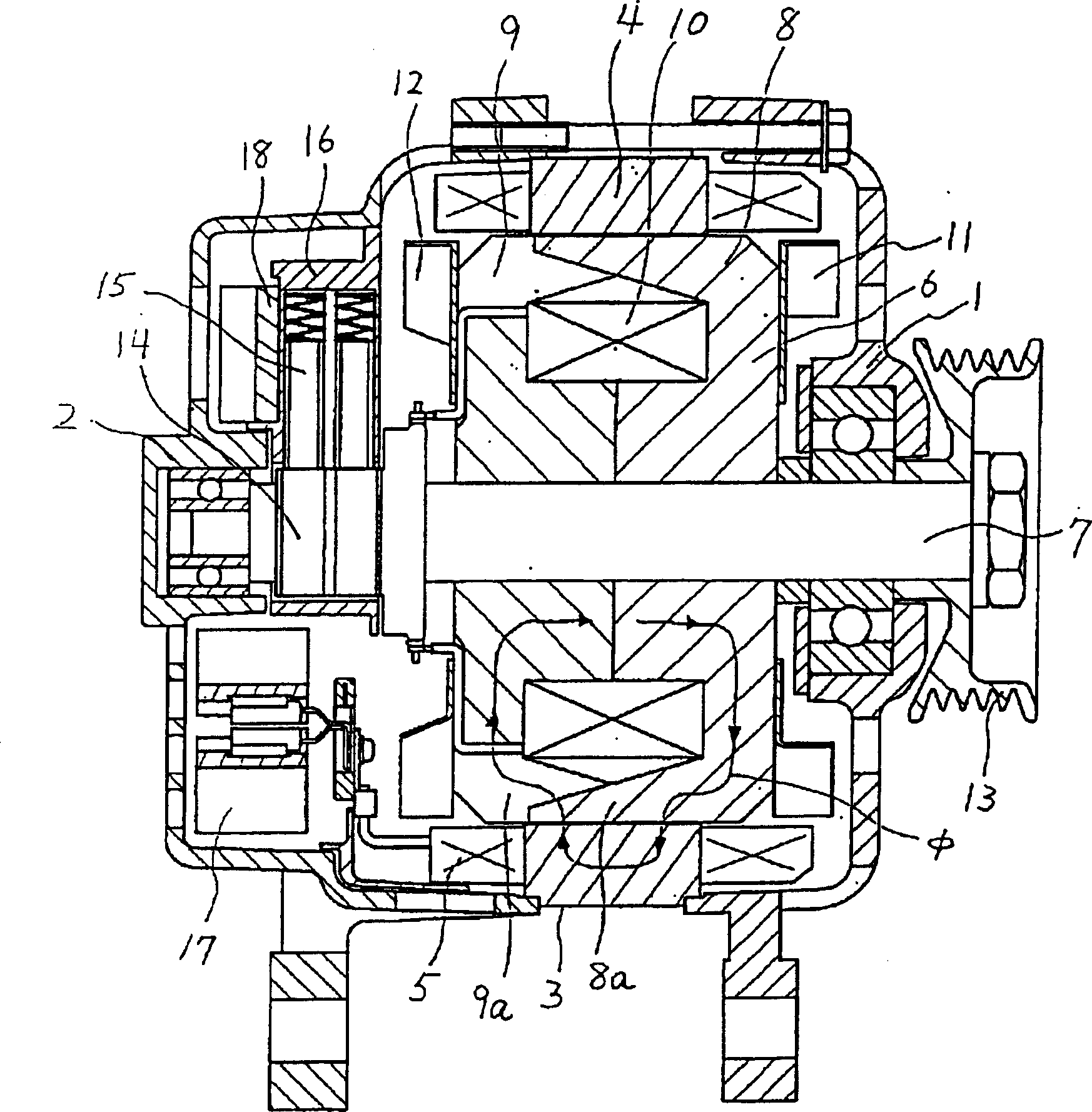
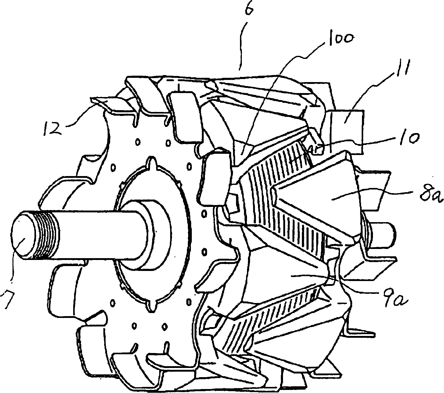
[0051] figure 1 is a cross-sectional view of the vehicle alternator according to Embodiment 1 of the present invention, figure 2 yes figure 1Oblique view of the middle rotor. In the figure, 1 is the front bracket, 2 is the rear bracket, and 3 is the stator held by the front bracket 1 and the rear bracket 2, which consists of the stator core 4 and the winding wire inserted into the slot of the stator core 4. Winding 5 constitutes.

[0052] 6 is the rotor tightly fixed on both ends of the rotating shaft 7 supported by the front bracket 1 and the rear bracket 2, consisting of the first rotor core 8; the second rotor core 9; the excitation coil wound between the two rotor cores 8 and 9 Coil 10; the fan 11,12 that is arranged on the back side of two rotor cores; the belt pulley 13 that is arranged on the outside of the front bracket 1 side of the rotating shaft 7; Ring 14 constitutes.

[0053] 15 is a brush that supplies current to the slip ring 14, 16 is a brush holder for...

Embodiment approach 2

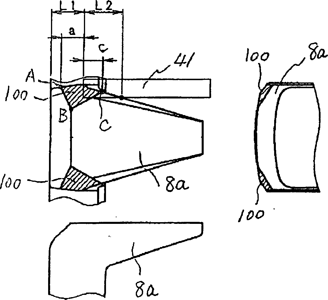
[0063] In this embodiment, the position of the point C on the twisted inclined portion of the pole piece 8a according to the first embodiment will be described in detail. This point C is preferably at the position where the tops of the T-shaped bars 41 of the stator core 4 overlap radially, Figure 5 It is the pole piece 8a leakage magnetic flux diagram of the rotor 6. As shown in the figure, there is a magnetic leakage flux φ leaking from the pole piece 8a to the pole piece 9a through the T-bar 41 at the radial overlap of the top end of the pole piece 8a and the T-shaped bar 41 . This is because the pole piece 8a and the top end of the T-shaped bar 41 face the cause with a small radial gap. However, in the present embodiment, the top end of the T-shaped bar 41 is overlapped on the chamfered portion 100 of the pole piece 8a. Larger, the leakage flux can be reduced.

[0064] In more detail, in image 3 Among them, the overlapping amount C is preferably equal to or less than...

Embodiment approach 3

[0066] Figure 7 It is an enlarged view of the pole piece 8a of the rotor 6 of the vehicle alternator according to Embodiment 3 of the present invention. In this embodiment, as shown in the figure, the distance between two points B on the tapered starting line of the base shoulders of the two chamfers 100 formed by the pole piece 8a is denoted as S, and the distance S should be formed It is approximately half or less of the circumferential width H of the pole piece 8a.

[0067] Figure 8 is the relationship between distance S and electromagnetic noise. In the figure, the vertical axis represents the sound level (sound pressure level) (dB) of the generator electromagnetic noise. The horizontal axis represents the distance S. As shown in the figure, it is clear that the distance S is less than half of the circumferential width H of the pole piece 8a, and the electromagnetic noise is small, below 78dB, but when the distance S is more than half of the circumferential width H o...


PUM


Abstract

The invention provides a high-power vehicle AC generator, able to reduce the noise called wind noise and electromagnetic noise, improving the rotor magnetic circuit. Its character: it has the chamferangle part composed of the surface which links the following three points: point B, developed on the circumferential end surfaces of the base shoulder of the pole boots(18a) and (19a) and developed on the subulate starting line by the peripheral surfaces of the base shoulder, point C on the warping tilt part of the pole boots (8a) and (9a), and point an on the circumferential end surfaces of the pole boots (8a) and (9a) L1 / 4-7í‡L1 / 8 distant from the end surface of the stator iron core when the distance between the base side end surface of the pole boots (8a) and (9a) and the end surface of the stator iron core is set as L1.

Description

technical field [0001] The present invention relates to a vehicle alternator driven by a vehicle internal combustion engine. Background technique [0002] To ensure optimum performance, vehicle alternators are cooled during operation to keep the entire generator below a certain temperature limit. As a cooling method, a fan is fixed on the disc of the magnetic pole wheel of the rotor and arranged inside the housing so that the cooling fan faces the stator winding so that sufficient heat can be radiated. As a result, the degree of cooling is improved, and the output power of the alternator can be increased. However, there is a problem in that, due to the vortex flow of the air in the casing, wind noise is large. In order to solve such a problem, the following proposals have been made conventionally. [0003] Figure 14 is, for example, a sectional view of a conventional vehicle alternator disclosed in JP-A-5-161286, Figure 15 shown as Figure 14 Oblique view of 1 pole whee...

Claims


Application Information

Patent Timeline
Patent Type & Authority Applications(China)
IPC IPC(8): H02K1/24H02K5/24H02K19/16
Inventor 大桥笃志浅尾淑人
Owner MITSUBISHI ELECTRIC CORP
Why Eureka
Try Eureka