Network cable connector

a network cable and connector technology, applied in the direction of coupling device connection, coupling device details, two-part coupling devices, etc., can solve the problems of increasing the diameter of the network cable, the rear end of the binding tail of the network cable connector may not fit the required connection, and the wire connection process is relatively inconvenient, so as to improve the dustproof and aesthetic effect, the effect of connecting wires and improving the effect of aesthetics

Active Publication Date: 2018-09-20
JYH ENG TECH
View PDF8 Cites 4 Cited by
  • Summary
  • Abstract
  • Description
  • Claims
  • Application Information

AI Technical Summary

Benefits of technology

[0026]Therefore, the present invention makes the process of connecting wires more easily by lifting open the main body and prevents the network cable from shaking by adopting the hollow compression device. In addition, there is no gap between the rear end of the network cable connector and the network cable to improve the dustproof and aesthetic effects. Further, the direction changing member and the hollow compression device are linked, so that after the network cable is bent, the network cable will not be shaken by external force. With the feature of the detachable direction changing member, users may install or un-install the network cable more flexibly without the need of changing the network cable connector, so as to improve the convenience of use.

Problems solved by technology

However, almost all of the conventional network cable connectors are fully sealed and just provide a hole for connecting the network cable, so that the wire connection process is relatively inconvenient.
For a high frequency network signal transmission or a compact assembly configuration, the diameter of a network cable is increased or decreased accordingly, so that the binding tail at the rear end of network cable connector may not fit the required connection.
If the diameter of the binding tail has a diameter in compliance with the network cable of a larger diameter and a user wants to use a network cable with a smaller diameter, then a too-large gap will be formed between the binding tail and the wire, and a protection effect cannot be achieved.
On the other hand, a wire with a too-large diameter cannot be tightened securely at the tail, so that the network cable connector cannot be used.
Although some manufacturers has add two different sizes for the binding tail base to overcome the aforementioned problem, yet the binding tail is smaller and may fall out or be missing unintentionally.
Although these methods can achieve the effect of fixing the network cable, yet the portion proximate to the rear end of the network cable connector, and the portion between the rear end of the network cable connector and the network cable still has a gap, so that foreign substances such as external dusts may enter from the gap or affect the signal transmission quality adversely.
In addition, the network cable may be shaken freely at the rear end of the network cable connector, and such free loosened end not just affects the aesthetic appearance of the network cable connector only, but also makes user to have the doubt of whether or not the network cable is fixed securely.
In addition, the aforementioned structural design of the network cable connector has a length greater than the ordinary network cable connector, and it is necessary to bend the network cable to fit a limited using environment with a smaller space, and the bent network cable may create an issue of aligning the core lines at the bent position or having a wrong alignment and may even damage the network cable.
However, the aforementioned bending methods have a problem, since the network cable connector having the bent tail cover is different from a general network cable connector.
In other words, the network cable connector installed with the bent tail cover cannot be remove the bent tail cover freely, so that it is necessary to bend network cable first and the wire cannot exit from the network cable connector directly.
Obviously, such application is very inconvenient and troublesome.

Method used


Image

  • Network cable connector
  • Network cable connector
  • Network cable connector

Examples


Embodiment Construction

[0039]The above and other objects, features and advantages of this disclosure will become apparent from the following detailed description taken with the accompanying drawings.

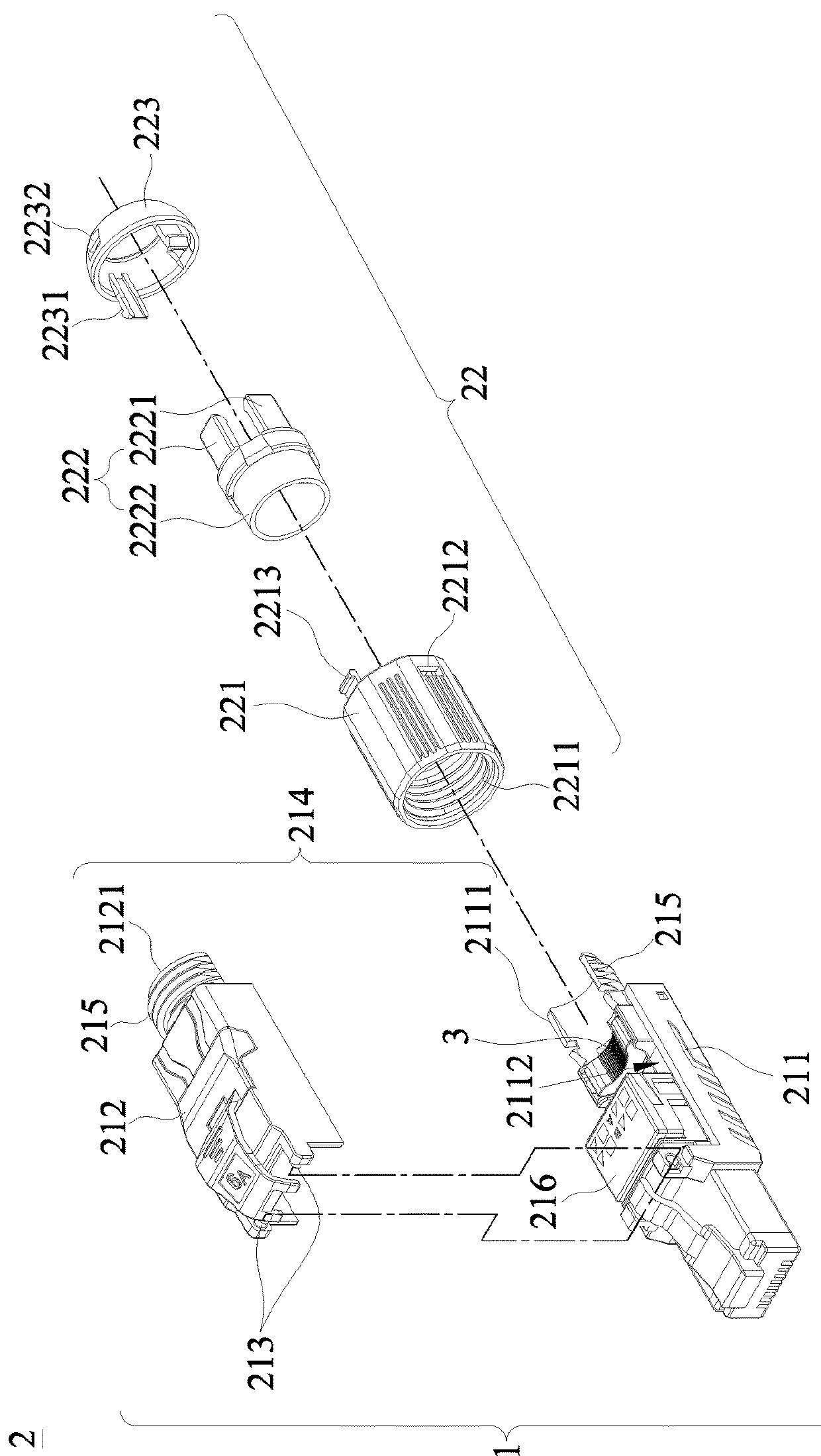
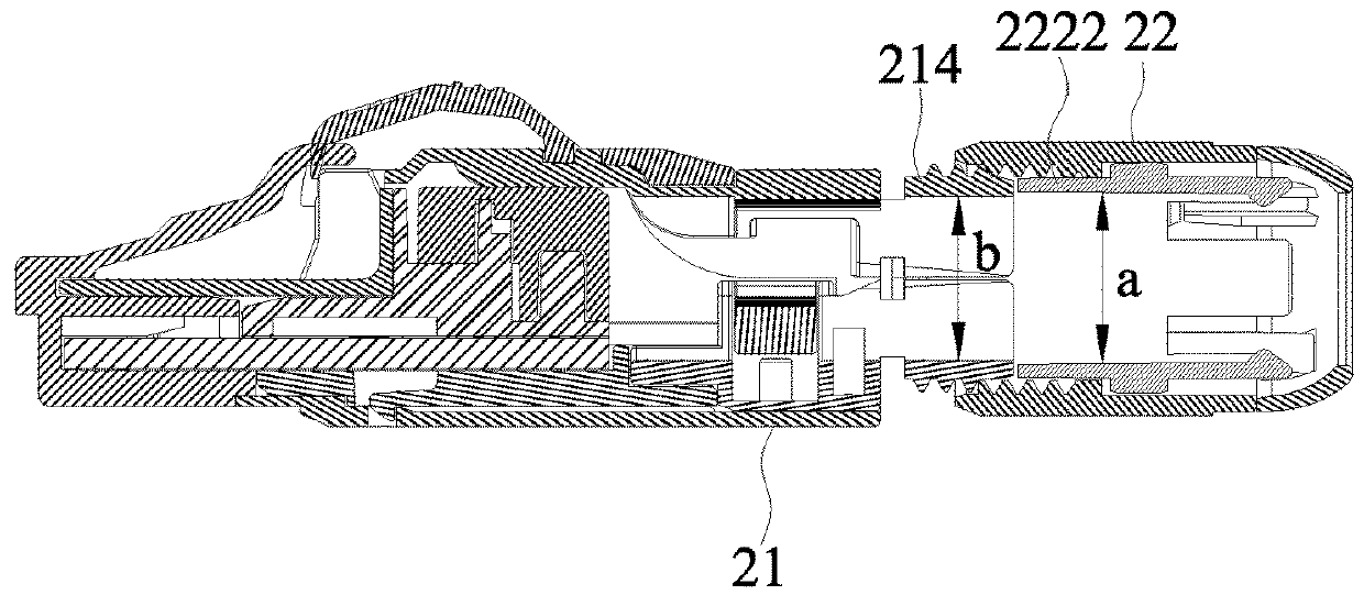
[0040]With reference to FIGS. 2, 5A-5C and 6 for the exploded view of a network cable connector of the first embodiment of the present invention and the schematic views of connecting wires, operating, binding or applying force to bind the network cable connector in accordance with the first embodiment of the present invention respectively, the network cable connector 2 comprises a main body 21, an elastic ejection block 3 and a hollow compression device 22. The main body 21 has a front end plugged into an external network jack (not shown in the figure) and an end plugged into an external network cable 4, and the main body 21 has a clamping base 211 and a clamping cover 212, and the clamping cover 212 is pivotally coupled to the clamping base 211, so that when the clamping cover 212 is opened, the network cable...


PUM


Abstract

A network cable connector includes: a main body having a containing portion and a pushing pipe communicated to each other; and a hollow compression device for passing a network cable and having a fastener, a clamping part and a sleeve member. The clamping part installed in the fastener has plural compression parts at an end of the clamping part, and the other end of the clamping part is a pushing part. The sleeve member covers the end of the fastener coupled to the main body and has a curved inner surface tapered from an end near the fastener to the other. When the hollow compression device and main body are secured by screwing, the pushing pipe pushes the pushing part to move the clamping part towards the sleeve member, and the compression parts compresses the curved inner surface of the sleeve member to clamp the network cable tightly.

Description

CROSS-REFERENCE TO RELATED APPLICATIONS[0001]This non-provisional application claims priority under 35 U.S.C. § 119(a) on Patent Application No(s).106203790 filed in Taiwan, R.O.C. on Mar. 17, 2017, the entire contents of which are hereby incorporated by reference.FIELD OF INVENTION[0002]The present invention relates to the field of network cable connectors, in particular to a network cable connector capable of tightening and fixing a network cable and providing both aesthetic and dustproof effects in addition of connecting the network cable with the connector more conveniently.BACKGROUND OF INVENTION1. Description of the Related Art[0003]Network cable connector with the capability of improving the overall network jumper property has been used extensively. However, almost all of the conventional network cable connectors are fully sealed and just provide a hole for connecting the network cable, so that the wire connection process is relatively inconvenient.[0004]For a high frequency ...

Claims


Application Information

Patent Timeline
Patent Type & Authority Applications(United States)
IPC IPC(8): H01R13/502H01R24/64H01R13/52H01R13/512H01R13/58H01R13/506
CPCH01R13/5025H01R24/64H01R13/5205H01R13/512H01R13/582H01R13/506H01R13/5833H01R2107/00H01R2201/04H01R13/501H01R13/59
Inventor LIN, YEN-LIN
Owner JYH ENG TECH
Why Eureka
Try Eureka