Battery system and method for the operation thereof

a battery system and battery technology, applied in the field of battery systems, can solve the problems of hardly available charging stations with a rated voltage of more than 800 v at present, and achieve the effects of simple and quick repair, safe assembly, disassembly and transportation of the battery system

Active Publication Date: 2018-09-27
DR ING H C F PORSCHE AG
View PDF10 Cites 3 Cited by
  • Summary
  • Abstract
  • Description
  • Claims
  • Application Information

AI Technical Summary

Benefits of technology

[0010]It is therefore an object of the invention to provide a battery system having a high rated voltage and that can be charged using charging devices whose output voltage is lower than the rated voltage of the battery system. It is a further object of the invention to provide a battery system of this kind that can be repaired simply and quickly after an internal short circuit. A further object consists in being able to assemble, disassemble and transport the battery system safely.
[0011]The present invention provides a HV battery, in particular for a vehicle. The HV battery has an internal isolation such that no voltage is applied to the connections. The assembly, disassembly and transport of the battery are therefore safe. The HV battery comprises a series circuit of a plurality of cells, which are divided into sections. Conductors connect the positive and negative connections of the cells to an interface. The interface also has poles for connection to the intermediate electrodes of the battery.
[0012]When the battery is in the discharge mode, it is connected to the on-board converter. The intermediate electrodes are connected in series with intermediate fuses between the connections on the other side of the interface. The intermediate fuses are arranged in this way outside of the battery housing, which reduces the weight and size thereof.
[0013]A divided charging connection system is further provided. In the charge mode of the battery, a plurality of charging devices are each connected to a battery section using the intermediate electrodes in order to charge the sections in parallel. This makes it possible to use less powerful charging devices having a lower voltage range.
[0020]The fuses protect the modules of the battery system against damage from overvoltage or to excessive currents. Suitable fuses are known in principle to those skilled in the art. Examples are safety fuses, electronic fuses, self-resetting fuses such as bimetal fuses or PTC thermistors, line circuit breakers, etc.

Problems solved by technology

Charging stations having a rated voltage of more than 800 V are hardly available at present.

Method used


Image

  • Battery system and method for the operation thereof
  • Battery system and method for the operation thereof
  • Battery system and method for the operation thereof

Examples


Embodiment Construction

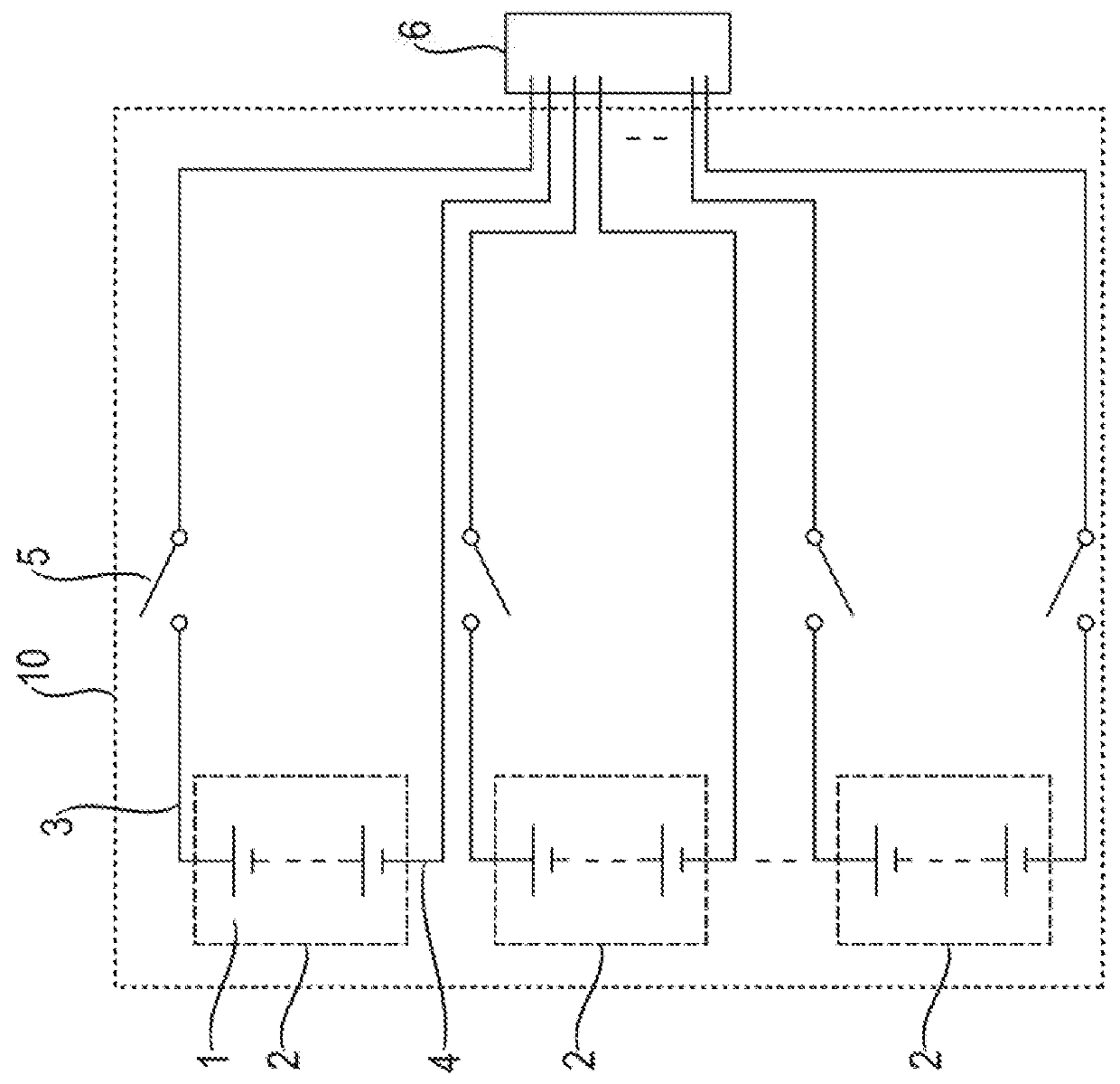
[0030]FIG. 1 shows a battery 10, which contains M cells connected in series, said cells being divided into N sections or modules 2. A conductor 4 leads from the negative pole of the (i*M / N+1)th (i=1 . . . N−1) cell to the interface 6 of a HV connection. A further conductor 3 leads from the positive pole of the (i*M / N)th (i=1 . . . N−1) cell to the interface 6 of a HV connection. The interface 6 has 2× N poles, two for the positive pole and the negative pole of the battery 10 and the rest for the intermediate poles in the battery 10. Switches 5 are provided in the conductors 3 that connect the positive poles of the modules 2 to the interface 6, said switches being open when the contacts of the interface 6 are open, that is to say are not connected either to a load or to a charging device. In the embodiment illustrated in FIG. 1, another switch 5 is additionally provided in the conductor 4, said switch connecting the negative pole of the last of the cascading modules 2, that is to say...


PUM

PropertyMeasurementUnit
voltagesaaaaaaaaaa
rated voltageaaaaaaaaaa
voltagesaaaaaaaaaa

Abstract

A battery system, in particular for a motor vehicle, to a power supply comprising the battery system for an electric machine, in particular a vehicle drive, and to a method for charging the battery system.

Description

CROSS-REFERENCE TO RELATED APPLICATIONS[0001]This application claims priority to German Patent Application No. DE 10 2017 106 058.8, filed Mar. 21, 2017, which is incorporated by reference herein in its entirety.FIELD OF THE INVENTION[0002]The invention relates to a battery system, in particular for a motor vehicle, to a power supply comprising the battery system for an electric machine, in particular a vehicle drive, and to a method for charging the battery system.BACKGROUND OF THE INVENTION[0003]A motor vehicle that has and uses at least one electric motor for driving or moving is referred to as an electric vehicle or a hybrid vehicle. In this case, during a driving operation of the motor vehicle, the at least one electric motor can be supplied with electrical energy from at least one electrical energy store, which can also be referred to as a battery or rechargeable battery. Said at least one electrical energy store can be, for example, a high-voltage battery (HV battery). Said h...

Claims


Application Information

Patent Timeline
Patent Type & Authority Applications(United States)
IPC IPC(8): B60L11/18H02J7/00H01M10/44H01M2/34H01M50/51
CPCB60L11/1838B60L11/1816B60L11/1868H02J7/0026H01M10/441H01M2/348H01M2220/20H01M2200/103B60L53/14H01M10/4207H01M50/581H02J7/00308H02J7/00304H01M50/51B60L58/20H02J7/0031H02J7/0014Y02T10/70Y02T90/12Y02T10/7072Y02T90/14Y02E60/10B60L53/20B60L53/16B60L50/51H01M10/425B60Y2200/92B60Y2200/91
Inventor SCHMIDT, TIMFAURI, MIKELDIBOS, HERMANN
Owner DR ING H C F PORSCHE AG
Why Eureka
Try Eureka