Stacked waveguides having different diffraction gratings for combined field of view

Active Publication Date: 2018-09-27
MAGIC LEAP
View PDF3 Cites 96 Cited by
  • Summary
  • Abstract
  • Description
  • Claims
  • Application Information

AI Technical Summary

Benefits of technology

[0009]In a fourth aspect, a head-mounted display device is configured to project light to an eye of a user to display augmented reality image content. The head-mounted display device comprises a frame configured to be supported on a head of the user. The head-mounted display device additionally comprises a display disposed on the frame. At least a portion of the display comprises a plurality of waveguides. The waveguides are transparent and disposed at a location in front of the user's eye when the user wears the head-mounted display device su

Problems solved by technology

Because the human visual perception system is complex, it is challenging to produce AR technology that facilitates a comfo

Method used


Image

  • Stacked waveguides having different diffraction gratings for combined field of view
  • Stacked waveguides having different diffraction gratings for combined field of view
  • Stacked waveguides having different diffraction gratings for combined field of view

Examples


Embodiment Construction

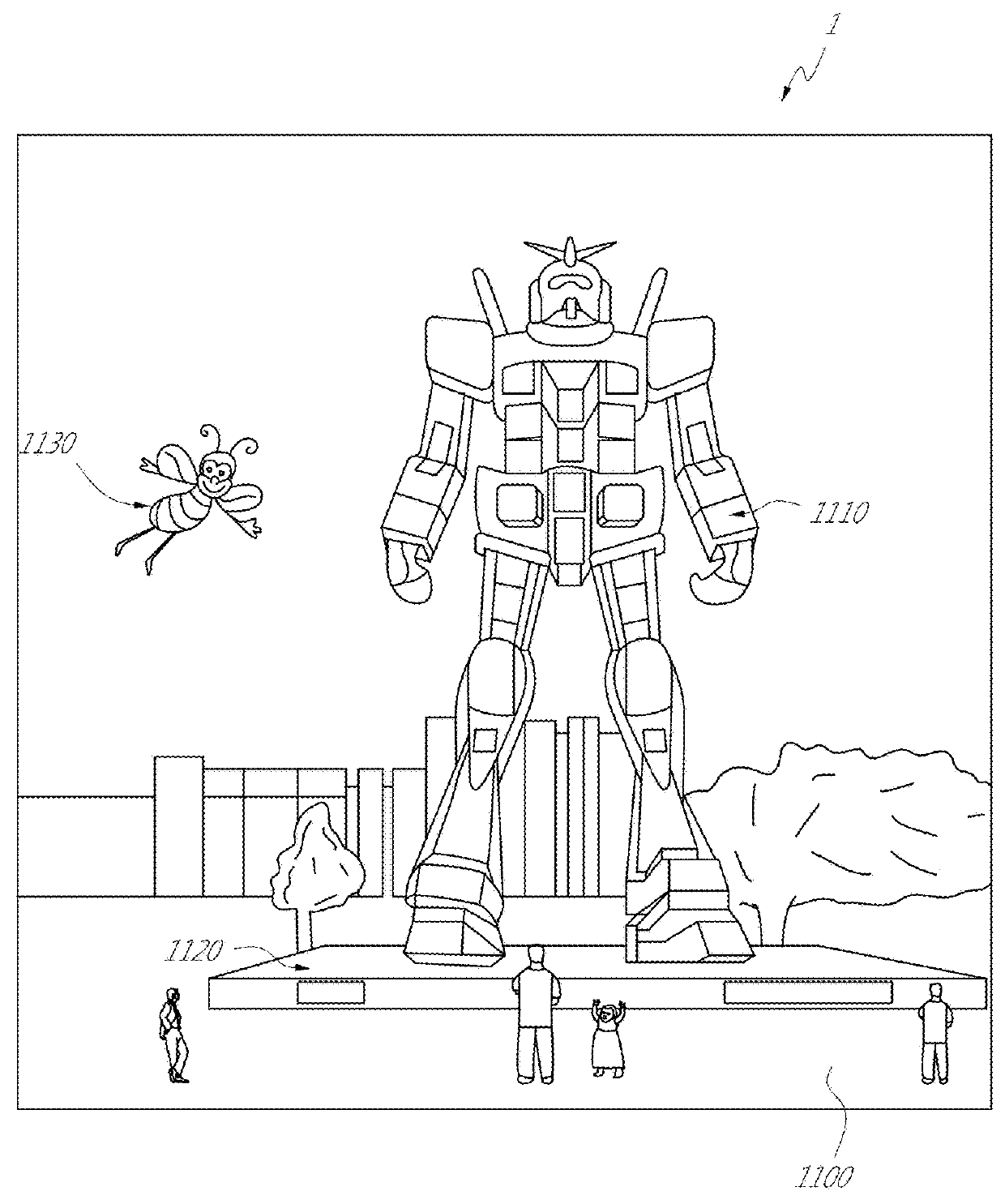
[0036]AR systems may display virtual content to a user, or viewer, while still allowing the user to see the world around them. Preferably, this content is displayed on a head-mounted display, e.g., as part of eyewear, that projects image information to the user's eyes. In addition, the display may also transmit light from the surrounding environment to the user's eyes, to allow a view of that surrounding environment. As used herein, it will be appreciated that a “head-mounted” display is a display that may be mounted on the head of a viewer.

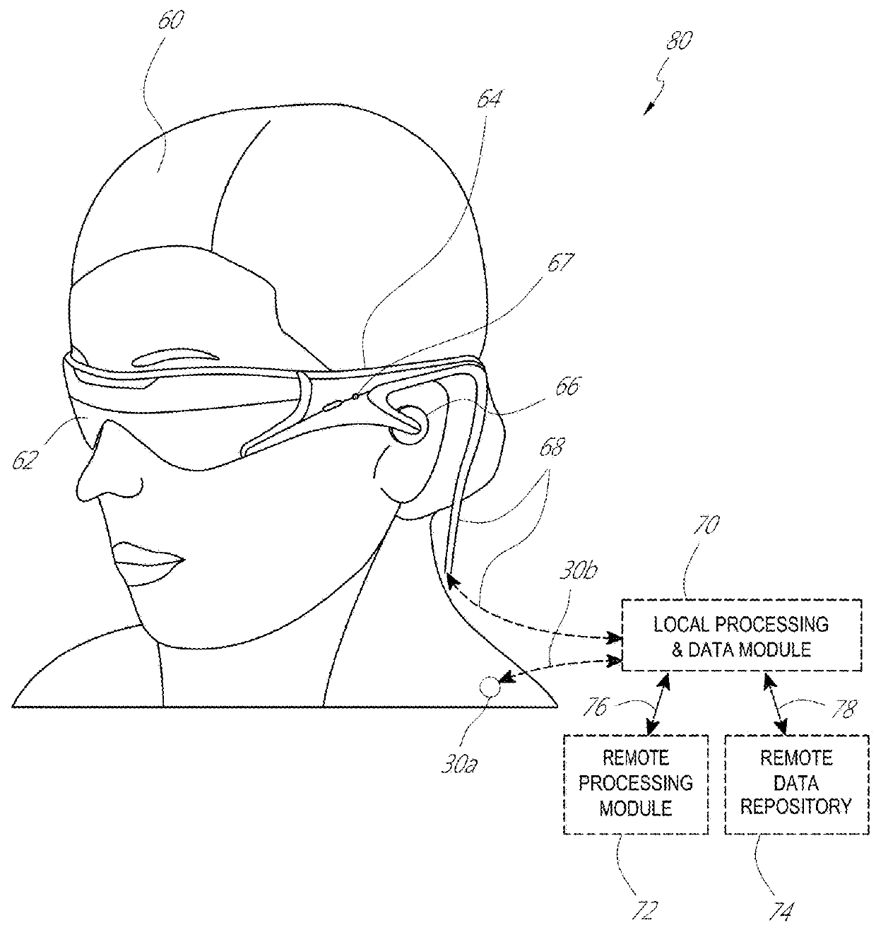
[0037]FIG. 2 illustrates an example of wearable display system 60. The display system 60 includes a display 70, and various mechanical and electronic modules and systems to support the functioning of that display 70. The display 70 may be coupled to a frame 80, which is wearable by a display system user or viewer 90 and which is configured to position the display 70 in front of the eyes of the user 90. The display 70 may be considered eyewear in ...


PUM


Abstract

In one aspect, an optical device comprises a plurality of waveguides formed over one another and having formed thereon respective diffraction gratings, wherein the respective diffraction gratings are configured to diffract visible light incident thereon into respective waveguides, such that visible light diffracted into the respective waveguides propagates therewithin. The respective diffraction gratings are configured to diffract the visible light into the respective waveguides within respective field of views (FOVs) with respect to layer normal directions of the respective waveguides. The respective FOVs are such that the plurality of waveguides are configured to diffract the visible light within a combined FOV that is continuous and greater than each of the respective FOVs

Description

INCORPORATION BY REFERENCE[0001]This application claims the priority benefit of U.S. Provisional Patent Application No. 62 / 474,529 filed on Mar. 21, 2017 entitled “STACKED WAVEGUIDES HAVING DIFFERENT DIFFRACTION GRATINGS FOR COMBINED FIELD OF VIEW,” which is incorporated by reference herein in its entirety.BACKGROUNDField[0002]The present disclosure relates to display systems and, more particularly, to augmented reality display systems comprising diffractive devices based on cholesteric liquid crystal.Description of the Related Art[0003]Modern computing and display technologies have facilitated the development of systems for so called “virtual reality” or “augmented reality” experiences, in which digitally reproduced images or portions thereof are presented to a user in a manner wherein they seem to be, or may be perceived as, real. A virtual reality, or “VR”, scenario typically involves the presentation of digital or virtual image information without transparency to other actual re...

Claims


Application Information

Patent Timeline
IPC IPC(8): G02B6/34G02B6/10G02F1/29G02F1/1343G02B27/01H04N9/31
CPCG02B6/34G02B6/10G02F1/292G02F1/134309G02B27/0172G02B27/0189H04N9/3129G02F2201/305G02F2203/22F21Y2113/10G02B27/0093G02B6/0016G02B6/0076G02B6/29316G02B2027/0123G02B2027/0127G02B2027/0134G02B2027/0185G02B2027/0187G02B27/4261G02B5/1833G02B5/1842
Inventor OH, CHULWOOPARTHIBAN, VIK
Owner MAGIC LEAP
Why Eureka
Try Eureka