
Vehicle travel assistance system

a technology of vehicle travel assistance and vehicle, which is applied in the direction of braking systems, automatic initiations, etc., can solve the problems that the collision between the vehicle and the obstacle cannot be avoided, and achieve the effect of reducing the difference in braking force between the outer wheel and the inner wheel, increasing and correcting and reducing the braking force of the outer wheel

Active Publication Date: 2018-10-04
ADVICS CO LTD
View PDF3 Cites 5 Cited by
  • Summary
  • Abstract
  • Description
  • Claims
  • Application Information

AI Technical Summary

Benefits of technology

The patent text describes a system that controls the yawing motion of a vehicle by adjusting the braking force on the inner and outer wheels. By distributing the target yawing moment equally, the system achieves a smooth yawing motion without affecting the overall braking force. The system also ensures that the difference in braking force between the inner and outer wheels is controlled, which prevents the vehicle from stopping or decelerating incorrectly during the yawing motion. Additionally, when the steering wheel is operated by the driver, the system reduces the difference in braking force between the inner and outer wheels to facilitate a smooth yawing motion.

Problems solved by technology

However, even if the vehicle is decelerated by the execution of the deceleration control, in some cases, collision between the vehicle and the obstacle may not be avoided.
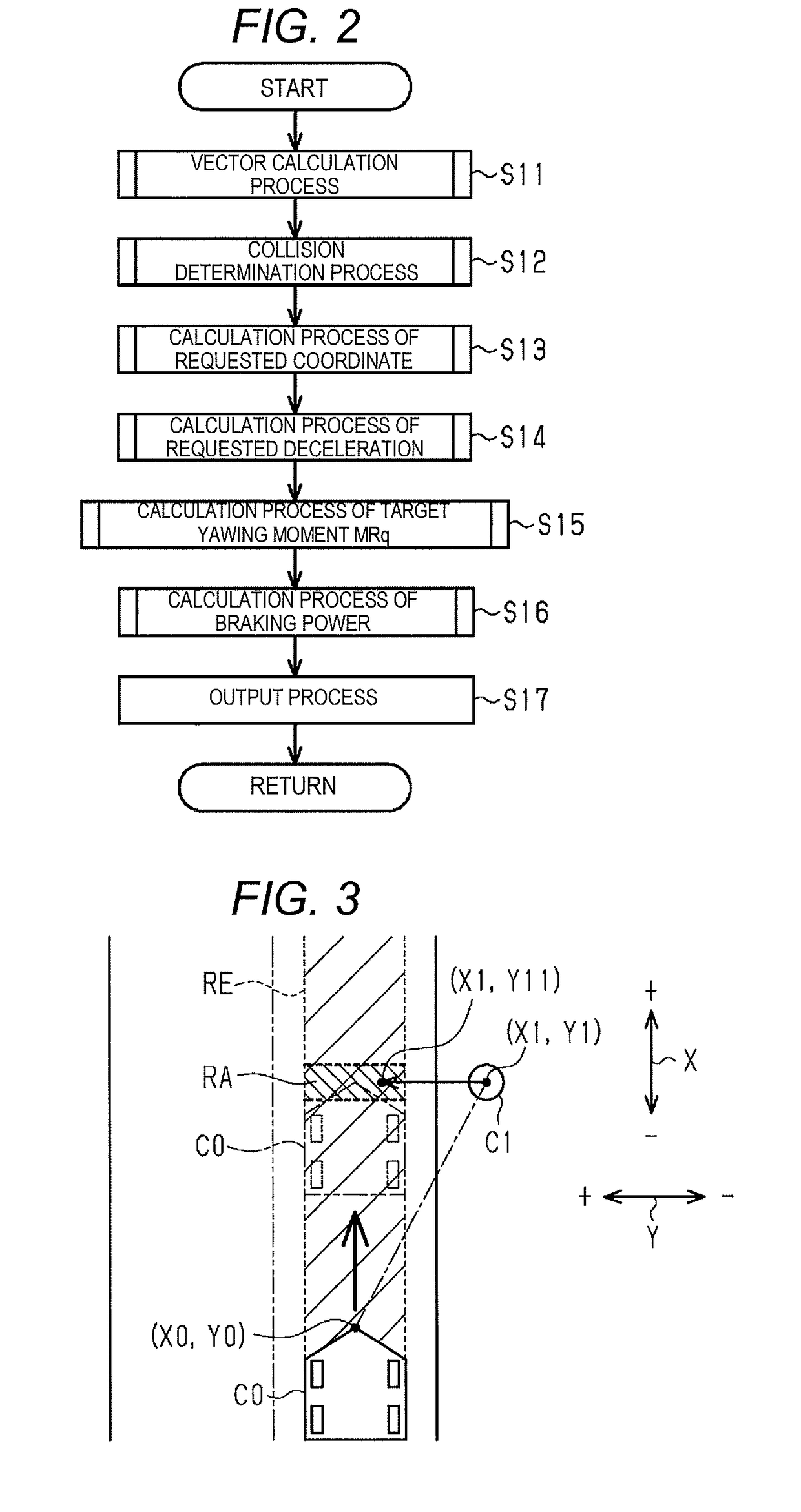
Therefore, in such a travel assistance system, when it is determined that collision between the vehicle and the obstacle cannot be avoided even if the vehicle is decelerated by the execution of the deceleration control, a target travel route in a mode of avoiding the obstacle is generated to cause the vehicle to travel along the same target travel route.

Method used


Image

  • Vehicle travel assistance system
  • Vehicle travel assistance system
  • Vehicle travel assistance system

Examples


first embodiment

[0047]Hereinafter, a first embodiment of a vehicle travel assistance system will be described with reference to FIGS. 1 to 13.

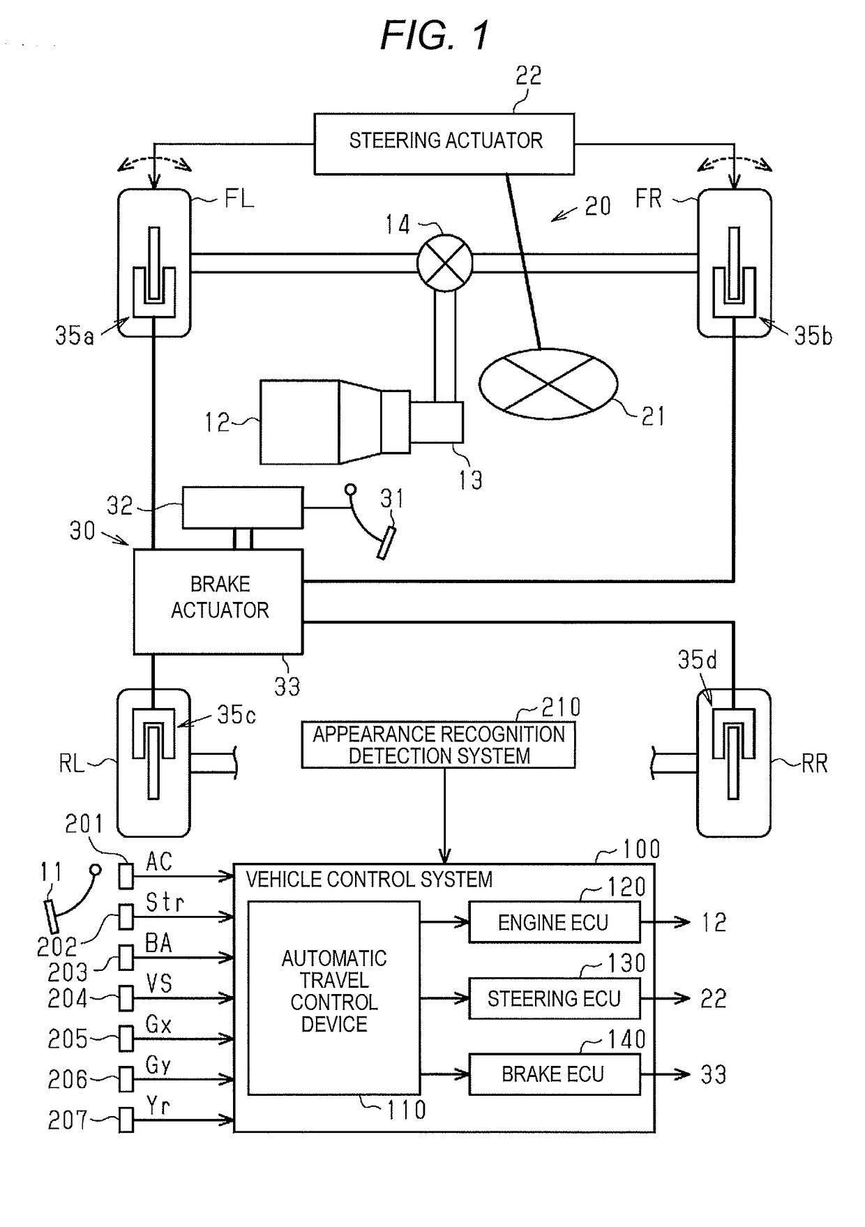
[0048]FIG. 1 illustrates a vehicle control system 100 equipped with an automatic travel control device 110 that is a vehicle travel assistance system of the embodiment, and a vehicle equipped with the vehicle control system 100. As illustrated in FIG. 1, the vehicle is a front wheel drive vehicle, a left front wheel FL and a right front wheel FR function as driving wheels, and a left rear wheel RL and a right rear wheel RR function as driven wheels. Further, the vehicle is equipped with an engine 12 as an example of a power source that outputs a drive torque according to the operation amount of an accelerator pedal 11 by the driver, and a speed change gear 13 in which a speed change ratio is changed in accordance with the vehicle body speed of the vehicle or the rotational speed of the engine 12. Further, the drive torque which is output from the speed change...

second embodiment

[0129]Next, a second embodiment embodying a vehicle travel assistance system will be described with reference to FIGS. 14 and 15. The vehicle travel assistance system of the embodiment is different from the first embodiment in that the moment control is executed even under the condition that the deceleration control is not executed. Therefore, in the following explanation, the parts different from the first embodiment will be mainly described, and the same or corresponding member configurations as those of the first embodiment are denoted by the same reference numerals, and repeated explanation will not be provided.

[0130]In the case of executing the moment control without executing the deceleration control, for example, the case of changing the traveling lane of the vehicle C0, a case where the road curves and the vehicle C0 is caused to be turned along the curve, and the like can be mentioned. In such a case, although the deceleration control flag FLG1 is set to OFF, the moment con...


PUM


Abstract

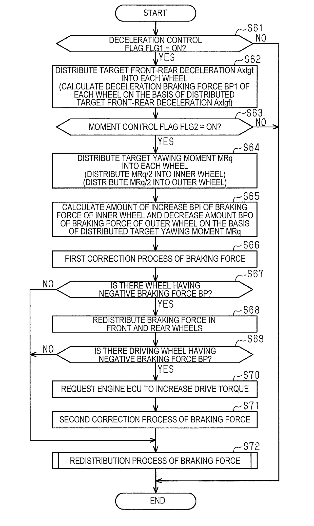
A vehicle travel assistance system includes distributing half of target yawing moment to inner wheels and distributing the rest to outer wheels; increasing the amount of increase in the braking force of the inner wheels as the target yawing moment distributed to the inner wheels increases, and increasing the amount of decrease in the braking force of the outer wheels as the target yawing moment distributed to the outer wheels increases; and causing the braking force of the inner wheels to increase according to the amount of increase in the braking force of the inner wheels, and causing the braking force of the outer wheels to decrease according to the amount of decrease in the braking force of the outer wheels.

Description

TECHNICAL FIELD[0001]The present invention relates to a vehicle travel assistance system that adjusts a yawing motion of a traveling vehicle by controlling a difference in braking force between a left wheel and a right wheel.BACKGROUND ART[0002]As a vehicle travel assistance system for avoiding a collision between an obstacle ahead of the vehicle and the vehicle, there is known a system which executes a deceleration control for applying a braking force to decelerate a vehicle. However, even if the vehicle is decelerated by the execution of the deceleration control, in some cases, collision between the vehicle and the obstacle may not be avoided. Therefore, in such a travel assistance system, when it is determined that collision between the vehicle and the obstacle cannot be avoided even if the vehicle is decelerated by the execution of the deceleration control, a target travel route in a mode of avoiding the obstacle is generated to cause the vehicle to travel along the same target ...

Claims


Application Information

Patent Timeline
Patent Type & Authority Applications(United States)
IPC IPC(8): B60T8/1755B60T7/12B60W30/09B60W10/06B60W10/188
CPCB60T8/17558B60T8/17551B60T8/17552B60T7/12B60W30/09B60W10/06B60W10/188B60W30/18109B60W10/04B60W10/184B60W30/02B60W2720/14B60W2710/182B60T2220/03B60T8/1755
Inventor OHMORI, YOSUKESHIOTA, MASAKIYAMADA, YOSUKEMORI, YUKIO
Owner ADVICS CO LTD
Learn More