Anomaly detector for self-location estimation device and vehicle

a self-location and anomaly detection technology, applied in the field of anomaly detection, can solve problems such as self-location errors

Active Publication Date: 2018-10-04
NIHON KENKI CO LTD
View PDF0 Cites 5 Cited by
  • Summary
  • Abstract
  • Description
  • Claims
  • Application Information

AI Technical Summary

Benefits of technology

[0007]The present invention can provide a technique to detect anomaly in a self-location estimation device installed in a vehicle without terrain information beforehand obtained. These and other issues, configurations and advantages will be apparent from a reading of the following

Problems solved by technology

Due to interference factors such as multipath or the like, an error may occur in a self-location using a GPS (Global Positioning System) signal.

Method used


Image

  • Anomaly detector for self-location estimation device and vehicle
  • Anomaly detector for self-location estimation device and vehicle
  • Anomaly detector for self-location estimation device and vehicle

Examples


first embodiment

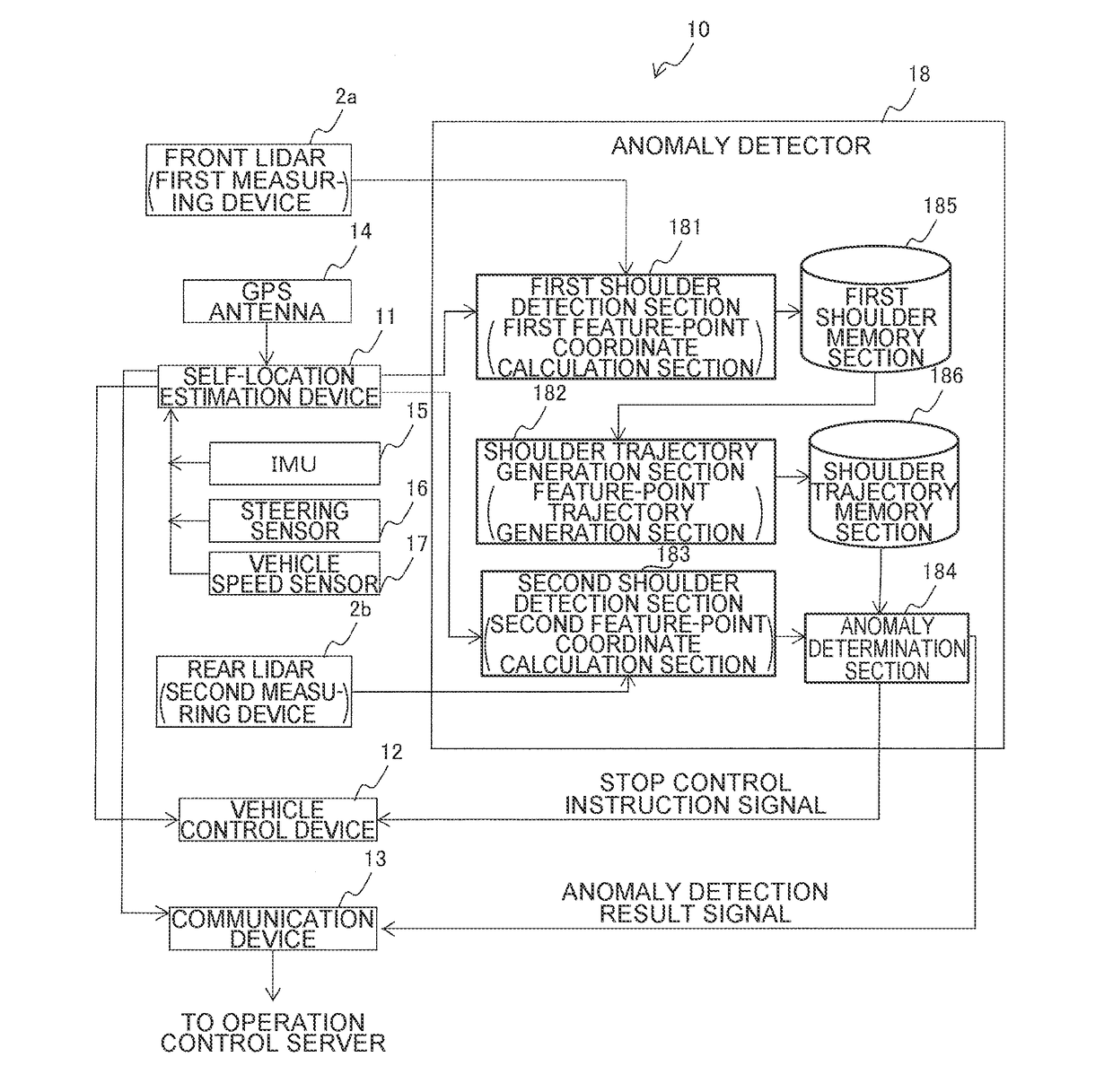
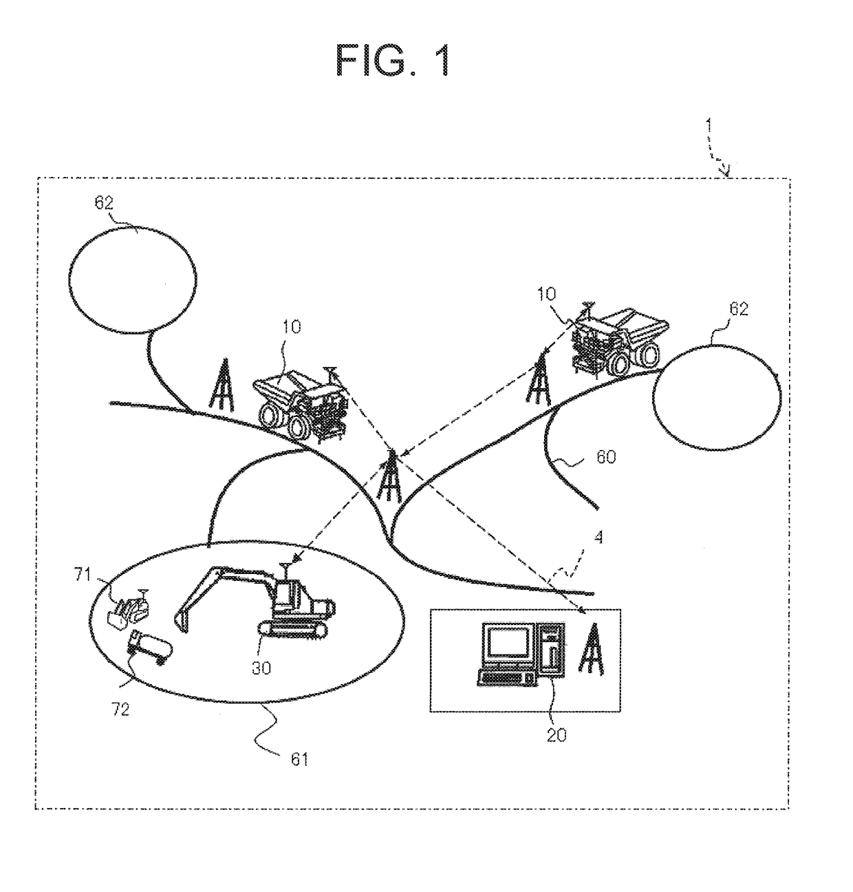
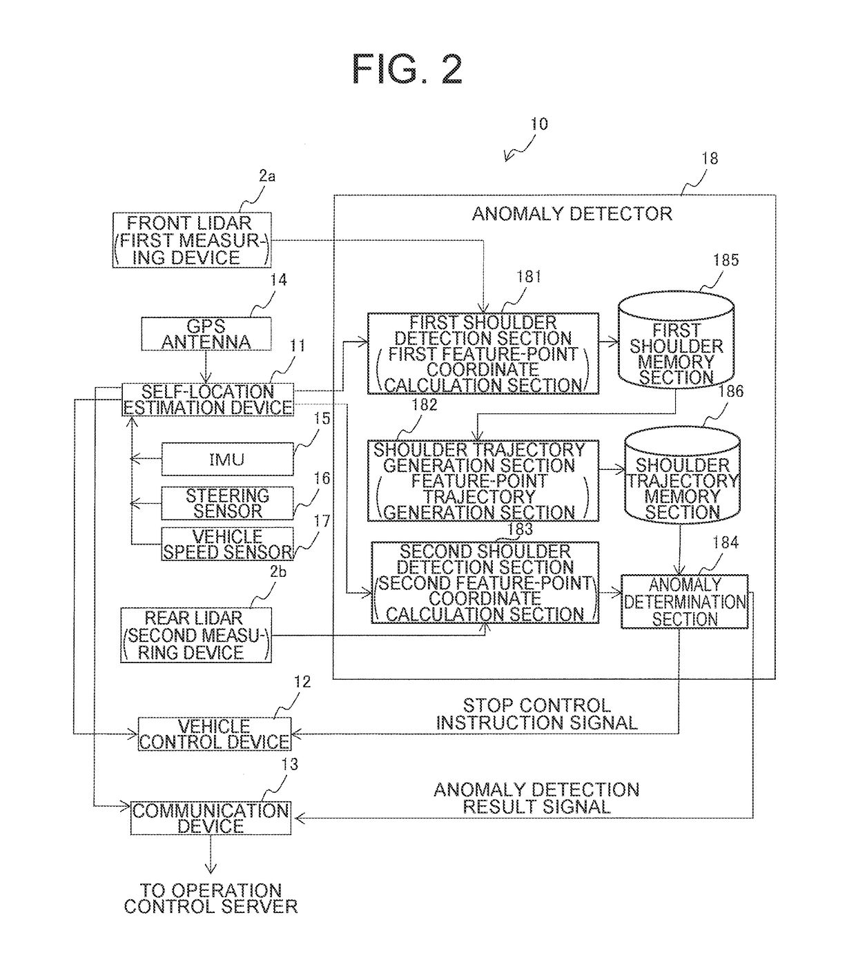
[0019]An autonomous travel system 1 illustrated in FIG. 1 is configured to include a communication connection over a wireless communication network 4 between a dump truck 10 illustrated as an example of mine working machines autonomously traveling and an operation control server 20 installed in an operation control center either close to or away from a quarry. A mine includes: loading sites 61 in which an excavator 30 performs excavation work and then loads excavated earth and ores onto the dump truck 10; dumping sites 62 in which the dump truck 10 dumps the burden it has hauled; and haul road 60 connecting the loading sites 61 with the dumping sites 62. The dump truck 10 receives operation control information from the operation control server 20 over the wireless communication network 4, and autonomously travels at a predetermined traveling speed on the haul road 60 in compliance with the operation control information.

[0020]Although one example described in the following descriptio...

second embodiment

[0065]FIG. 9 is a perspective schematic view illustrating the scanning surfaces of both of a front lidar 2a and a rear lidar 2b according to a second embodiment. FIG. 10 is a schematic top view illustrating the scanning surfaces of both of the front lidar 2a and the rear lidar 2b according to the second embodiment.

[0066]Regarding a point of difference of the second embodiment from the first embodiment, in the first embodiment, the front and rear lidars 2a, 2b are placed in the dump truck 10 such that the first road-surface scanning line L1a of the front lidar 2a and the second road-surface scanning line L1b of the rear lidar 2b are parallel to each other. In contrast to this, in the second embodiment, the front lidar 2a and the rear lidar 2b are installed to the dump truck 10 such that the first road-surface scanning line L1a and the second road-surface scanning line L1b cross each other in front of the vehicle and also within vehicle-width limits. Incidentally, in the second embodi...


PUM


Abstract

A first measuring device measures a location of its own vehicle relative to each feature point on a surrounding structure around a road surface on which the vehicle. A first feature-point is provided which, based on output from the first measuring device, acquires coordinates of the each feature point expressed in a coordinate system of the first measuring device, and uses a self-location to convert the coordinates into an external coordinate. A feature-point trajectory generation section is provided to generate, based on the first coordinates, a trajectory of the feature point group. A second measuring device measures a location of its own vehicle relative to a feature point located rearward of the feature point measured by the first measuring device. An anomaly determination section is provided to determine that anomaly occurs in a self-location estimation device if the second coordinates are on the trajectory.

Description

TECHNICAL FIELD[0001]The present invention relates to a technique to detect anomaly in a self-location estimation device installed in a vehicle.BACKGROUND ART[0002]Due to interference factors such as multipath or the like, an error may occur in a self-location using a GPS (Global Positioning System) signal. To address this, as an example of techniques for detection of anomaly occurring in the self-location estimation processing, Patent Literature 1 discloses “A travel controlling apparatus of an unmanned vehicle comprising: a GPS receiver receiving a GPS signal so as to determine a vehicle position; an autonomous navigation computing device to position a position and azimuth of the vehicle on the basis of a traveling direction and a traveling distance of the vehicle; a position measuring portion calculating a present position and azimuth of the vehicle on the basis of the respective measured results of the GPS receiver and the autonomous navigation computing device; and a travel con...

Claims


Application Information

Patent Timeline
Patent Type & Authority Applications(United States)
IPC IPC(8): G01S19/48G05D1/02G01S19/22G01S19/50G01S17/87G01S17/875G01S17/89G01S17/931
CPCG01S19/48G05D1/0212G01S19/22G01S19/50G01S17/42G01S19/49G05D1/02G01S17/87G01S17/875G01S17/89G01S7/497G05D2201/021G01S17/931G01S19/485
Inventor ONO, YUKIHIKOISHIMOTO, HIDEFUMITANAKA, WATARU
Owner NIHON KENKI CO LTD
Why Eureka
Try Eureka