
Three-dimensional image processing apparatus, three-dimensional image processing method, and three-dimensional image processing program

Active Publication Date: 2018-10-04
FUJIFILM CORP
View PDF2 Cites 36 Cited by
  • Summary
  • Abstract
  • Description
  • Claims
  • Application Information

AI Technical Summary

Benefits of technology

The patent describes a method to create a clear and precise projection image for use in endoscope imaging. This method allows for faster processing and ensures that the desired features are retained. The technical effect of this invention is an improved ability to register and align images in real-time endoscopy procedures, leading to improved accuracy and reliability in medical diagnostics.

Problems solved by technology

In this case, since it is laborious to sequentially change the virtual endoscope display method manually to match movement of an actual endoscope, a method for estimating which place in the body a tip of the endoscope is located at to create a virtual endoscope image.
However, in order to enhance estimation accuracy or stability of a tip position of an endoscope, it is necessary to generate a large amount of virtual endoscope images, but a volume rendering process that is a process of generating virtual endoscope images takes a lot of time.
JP2013-192741A discloses a technique for generating a graphical structure from a three-dimensional image of bronchial tubes, and generating, with respect to each of a plurality of divergent points included in the graphical structure, a projection image obtained by projecting divergence destinations from the divergent point on a two-dimensional plane including the divergent point, but since the projection image is a schematic image indicating the divergence destinations and is not an image that correctly represents shapes or the like of holes of bronchial tubes, the projection image is not suitable for the above-described registration process with respect to the endoscope image.

Method used


Image

  • Three-dimensional image processing apparatus, three-dimensional image processing method, and three-dimensional image processing program
  • Three-dimensional image processing apparatus, three-dimensional image processing method, and three-dimensional image processing program
  • Three-dimensional image processing apparatus, three-dimensional image processing method, and three-dimensional image processing program

Examples


Embodiment Construction

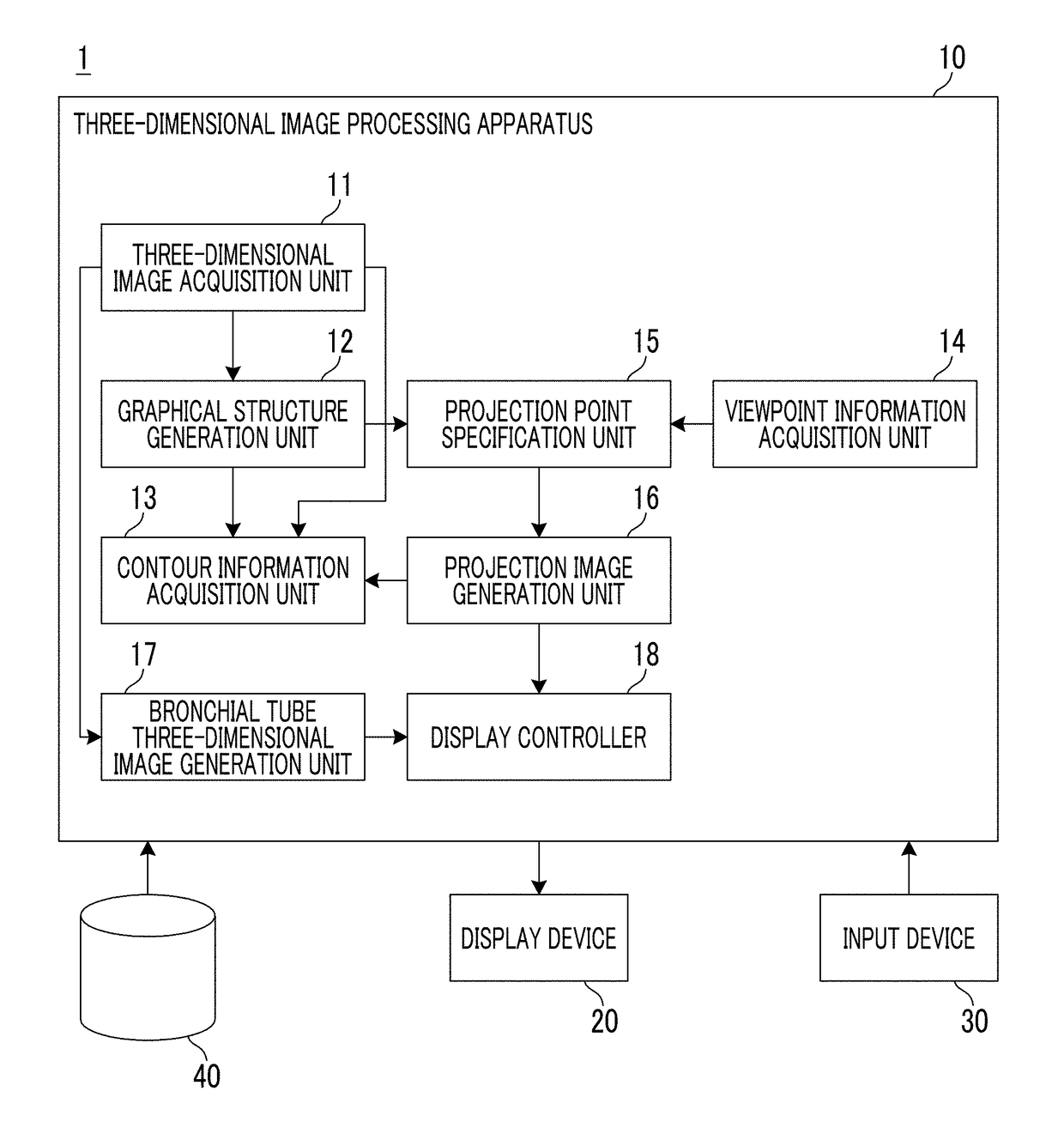
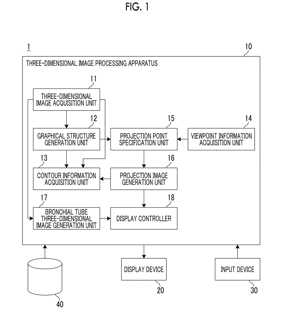
[0041]Hereinafter, an endoscope image diagnosis support system using an embodiment of a three-dimensional image processing apparatus, a three-dimensional image processing method, and a three-dimensional image processing program according to the present invention will be described in detail with reference to the accompanying drawings. FIG. 1 is a block diagram showing a schematic configuration of the endoscope image diagnosis support system according to this embodiment.

[0042]An endoscope image diagnosis support system 1 of this embodiment includes a three-dimensional image processing apparatus 10, a display device 20, an input device 30, and a three-dimensional image storage server 40, as shown in FIG. 1.

[0043]The three-dimensional image processing apparatus 10 is configured by installing a three-dimensional image processing program of this embodiment to a computer.

[0044]Further, the three-dimensional image processing apparatus 10 includes a central processing unit (CPU), a storage d...


PUM


Abstract

A three-dimensional image processing apparatus includes a three-dimensional image acquisition unit that acquires a three-dimensional image obtained by imaging a test object; a graphical structure generation unit that generates a graphical structure of a tubular structure included in the three-dimensional image; a contour information acquisition unit that acquires contour information on the tubular structure at each point on the graphical structure; a viewpoint information acquisition unit that acquires viewpoint information in the tubular structure; a projection point specification unit that specifies projection points from respective points on the graphical structure on the basis of the viewpoint information and the graphical structure; and a projection image generation unit that generates a projection image obtained by projecting the contour information at the projection points on a two-dimensional plane.

Description

CROSS-REFERENCE TO RELATED APPLICATIONS[0001]This application claims priority from Japanese Patent Application No. 2017-065096, filed on Mar. 29, 2017, and Japanese Patent Application No. 2017-182196, filed on Sep. 22, 2017, the disclosure of which are incorporated by reference herein in these entirety.BACKGROUNDField of the Invention[0002]The present invention relates to a three-dimensional image processing apparatus, a three-dimensional image processing method, and a three-dimensional image processing program for supporting insertion of an endoscope into a pipe line in the body such as a bronchial tube using a three-dimensional image obtained by imaging a test object.Related Art[0003]Recently, along with advances of an imaging apparatus, resolution of image data obtained by imaging using an imaging apparatus has been enhanced, and detailed analysis of a test object has become possible on the basis of the image data. For example, multi detector-row computed tomography (CT) is able ...

Claims


Application Information

Patent Timeline
IPC IPC(8): G06T15/20H04N7/18G06T7/00G06T19/00A61B1/267A61B34/20
CPCG06T15/205H04N7/183G06T7/0012G06T19/003A61B1/2676A61B34/20G06T2210/41G06T2207/10068G06T2207/30061A61B2034/2057A61B2034/2065A61B2017/00809G06T7/12A61B1/00194
Inventor HIRAKAWA, SHINNOSUKE
Owner FUJIFILM CORP
Learn More