Capsule, a system for preparing a potable beverage from such a capsule and use of such a capsule in a beverage preparation device

a technology of capsules and beverage preparation devices, which is applied in the field of capsules, can solve the problems of leakage, insufficient pressure in the enclosing member and outside the capsule, and insufficient increase of the pressure for increasing

Active Publication Date: 2018-10-11
KONINK DOUWE EGBERTS BV
View PDF4 Cites 12 Cited by
  • Summary
  • Abstract
  • Description
  • Claims
  • Application Information

AI Technical Summary

Benefits of technology

[0009]It is an object of the invention to provide an alternative sealing member which is relatively easy to manufacture, which is environmentally friendly if the capsule is disposed of after use and / or which provides a satisfactory sealing both at a relatively low fluid pressure if only a relatively small force is applied on the sealing member by means of the free end of the enclosing member (sometimes also called initial seal) and at a much higher fluid pressure if a higher force is applied (e.g. during brewing) by means of the free end of the enclosing member to the sealing member of the capsule, even in case of an enclosing member of which the free contact end is provided with radially extending open grooves.
[0046]In an embodiment of a system according to the invention wherein the plurality of radially extending open grooves are uniformly spaced relative to each other in tangential direction of the free contact end of the annular element of the beverage preparation device so that it is easier for a user to take out the capsule while a satisfactory seal between capsule and beverage preparation device can still be provided.

Problems solved by technology

If at the start of brewing, there would not exist a fluid sealing contact between the capsule and the enclosing member, leakage will occur.
However, if leakage occurs there is a real chance that the pressure in the enclosing member and outside the capsule will not sufficiently increase for increasing the force on the sealing member by means of the free end of the enclosing member if the manually operated or an automatic mechanism moves the enclosing member towards the capsule holder.

Method used


Image

  • Capsule, a system for preparing a potable beverage from such a capsule and use of such a capsule in a beverage preparation device
  • Capsule, a system for preparing a potable beverage from such a capsule and use of such a capsule in a beverage preparation device
  • Capsule, a system for preparing a potable beverage from such a capsule and use of such a capsule in a beverage preparation device

Examples


first embodiment

[0082]FIG. 4A shows a sealing member 28 forming an additional bearing at the outwardly extending flange 20 of a capsule 2 according to the invention. The sealing member and the remainder of the capsule body are made of the same plate material. The sealing member 28 comprises two spaced projections 50 and 51, each projecting axially from a base portion of the outwardly extending flange 20, to which base portion the cover 14 is attached, in a direction away from the cover 14. A plateau 52 is present between the two projections 50 and 51. The distance between the two projections 50 and 51 is such that the free contact end of the annular element 6 is squeezed between converging surfaces of the two projections 50 and 51 if the capsule is positioned in the enclosing member of the beverage preparation device and the enclosing member is closed by means of a closing member of the beverage preparation device. In the embodiment shown in FIG. 4A the plateau is positioned at a distance above the...

third embodiment

[0084]FIG. 4C shows a sealing member 28 at the outwardly extending flange 20 of a capsule according to the invention, which together with the side wall 16 of the aluminum capsule body forms an additional bearing for the enclosing member. The shown sealing member 28 comprises a projection 53 projecting from the outwardly extending flange 20 and an inclined, substantially flat plateau 52 between a rounded topmost end portion of the projection 53 and the side wall 16 of the aluminum capsule body. In this embodiment the bearing is formed by the projection 53, the plateau 52 and the side wall 16 of the aluminum capsule body. The distance between the top of the projection 53 and the side wall 16 is such that the free contact end of the annular element 6 is enclosed by the projection 53 and the side wall 16 of the aluminum capsule body if the capsule is positioned in the enclosing member of the beverage preparation device and the enclosing member is closed by means of a closing member of t...

seventh embodiment

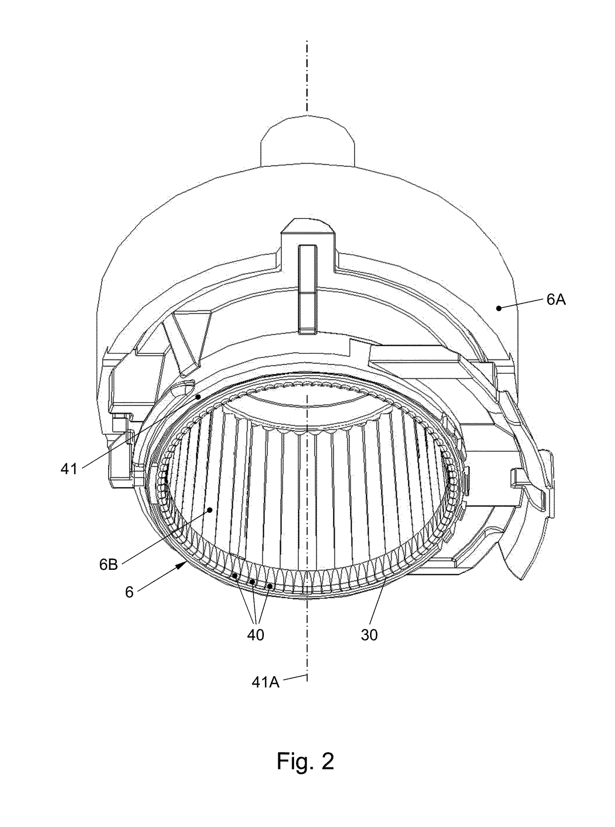
[0090]FIG. 4G shows a seal member 28 at the outwardly extending flange 20 of a capsule according to the invention. As also shown in FIG. 2, the enclosing member 6 of the beverage preparation device has an annular element 41 having a free contact end 30 with a plurality of radially extending open grooves 40 of which some are shown in FIG. 4G.

[0091]As in the examples shown in FIGS. 4A, 4B and 4F, the sealing member 28 has two spaced projections 50 and 51, each projecting axially from a base portion 21, 23 of the outwardly extending flange 20, to which base portions 21, 23 the cover 14 is attached, in a direction away from the cover 14. As in the example shown in FIG. 4F, a generally V-shaped plateau 52 having a rounded bottom is located between the two projections 50 and 51.

[0092]A difference compared with the examples shown in FIGS. 4A, 4B and 4F is that, in the example shown in FIG. 4G, a first one of the two projections 51 projects further from the base portions 21, 23 of the outwa...


PUM


Abstract

A capsule containing a substance for the preparation of a potable beverage. The capsule comprises an aluminum capsule body having a side wall and an outwardly extending flange and a sealing member at the outwardly extending flange for providing a fluid sealing contact with an enclosing member of a beverage preparation device. The beverage preparation device comprises an annular element having a free contact end which may be provided with a plurality of radially extending open grooves. The sealing member is integral with the outwardly extending flange and comprises at least one projection projecting from the outwardly extending flange. The projection comprising a projection top and is configured such that its projection top exerts a radial force on the free contact end of the annular element if the capsule is positioned in the enclosing member of the beverage preparation device and the enclosing member is closed by means of a closing member of the beverage preparation device.

Description

CROSS-REFERENCE TO RELATED APPLICATIONS[0001]This application is a continuation of International App. No. PCT / NL2016 / 050349 filed, which claims the benefit of and priority to International App. No. PCT / NL2015 / 050352 filed May 15, 2015, International App. No. PCT / NL2015 / 000018 filed May 15, 2015, International App. No. PCT / NL2015 / 050349 filed May 15, 2015, and International App. No. PCT / NL2015 / 050611 filed Sep. 3, 2015. The entire contents of all of which are incorporated herein by reference.BACKGROUND AND SUMMARY[0002]The invention relates to a capsule containing a substance for the preparation of a potable beverage by extracting and / or dissolving the substance by means of supplying a fluid under pressure into the capsule, wherein the capsule comprises an aluminum capsule body having a central capsule body axis, the aluminum capsule body being provided with a bottom, a side wall and an outwardly extending flange, the capsule further comprising an aluminum cover attached to the outwa...

Claims


Application Information

Patent Timeline
Patent Type & Authority Applications(United States)
IPC IPC(8): A47J31/36B65D85/804H04M1/72403H04M1/72445H04M1/72457
CPCA47J31/3695B65D85/8043B65D1/26B65D85/804A47J31/407A47J31/36B65D85/8064H04W48/02H04W4/50H04M1/72403H04M1/72445H04M1/72457A47J31/3623A47J31/3676A47J47/02B65D85/8049B65D77/20
Inventor DIJKSTRA, HIELKEGROOTHORNTE, AREND HENDRIKVAN GAASBEEK, ERIK PIETEROTTENSCHOT, MARC HENRIKUS JOSEPHKAMERBEEK, RALFEIJSACKERS, ARMIN SJOERDFLAMAND, JOHN HENRIHALLIDAY, ANDREW MICHAELHANSEN, NICHOLAS ANDREW
Owner KONINK DOUWE EGBERTS BV
Why Eureka
Try Eureka