Preheated sterilizing box for medical laboratory equipment

a sterilizing box and laboratory equipment technology, applied in the field of medical laboratory equipment, can solve the problems of not only tedious, unnecessary troubles, and large size of sterilizing boxes and heating boxes, and achieve the effects of preventing the breaking of uv lamps, increasing the utilization rate of heat, and increasing the contact area

Inactive Publication Date: 2018-10-11
CHAN KA YAN
View PDF2 Cites 7 Cited by
  • Summary
  • Abstract
  • Description
  • Claims
  • Application Information

AI Technical Summary

Benefits of technology

[0010]The advantage of the present invention is: the preheated sterilizing box for medical laboratory equipment of the present invention, comprising a body, a cover hinged to the body and an attachment device. A UV lamp is disposed inside the cover, and a transparent cover board is disposed on the cover to prevent breaking of the UV lamp. The body is separated by the separator and the heat guiding plate into a first chamber for holding preheated sterilizing equipment, a second chamber having temperature control circuitry, a third chamber disposed with a heating material and a fourth chamber disposed with a battery. An insulating layer is disposed at an inside wall of the first chamber and the third chamber, and a temperature sensor is embedded in the insulating layer, allo

Problems solved by technology

Normal sterilizing boxes and heating boxes are large and not portable, therefore the usual method is to first sterilize the equipment in the sterilizing box, and then move to the heating box for preheating.
This is not only tedious but also

Method used


Image

  • Preheated sterilizing box for medical laboratory equipment
  • Preheated sterilizing box for medical laboratory equipment

Examples


Embodiment Construction

[0015]The present invention is further explained below along with the accompanying drawings. The drawings are all simplified schematic diagrams which only illustrates the basic structure of the present invention, as such only the components material to the present invention are shown.

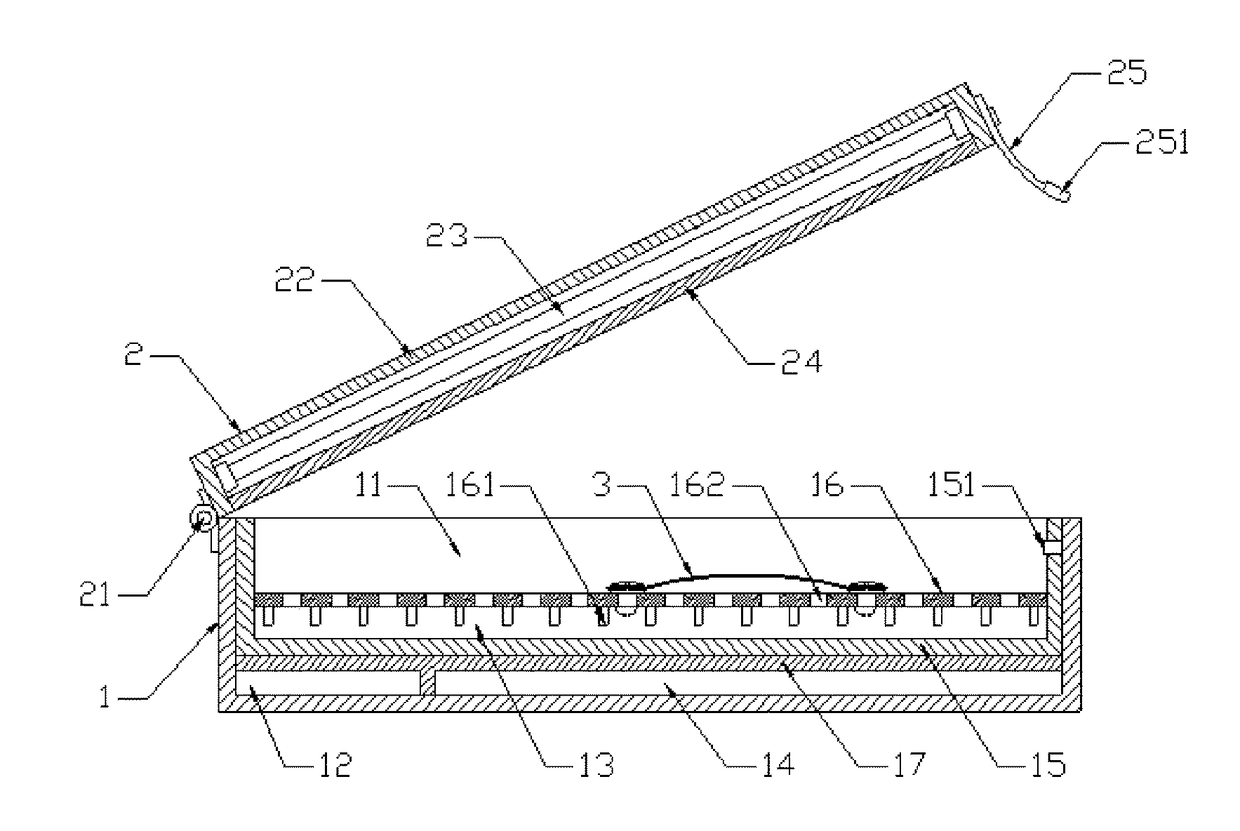
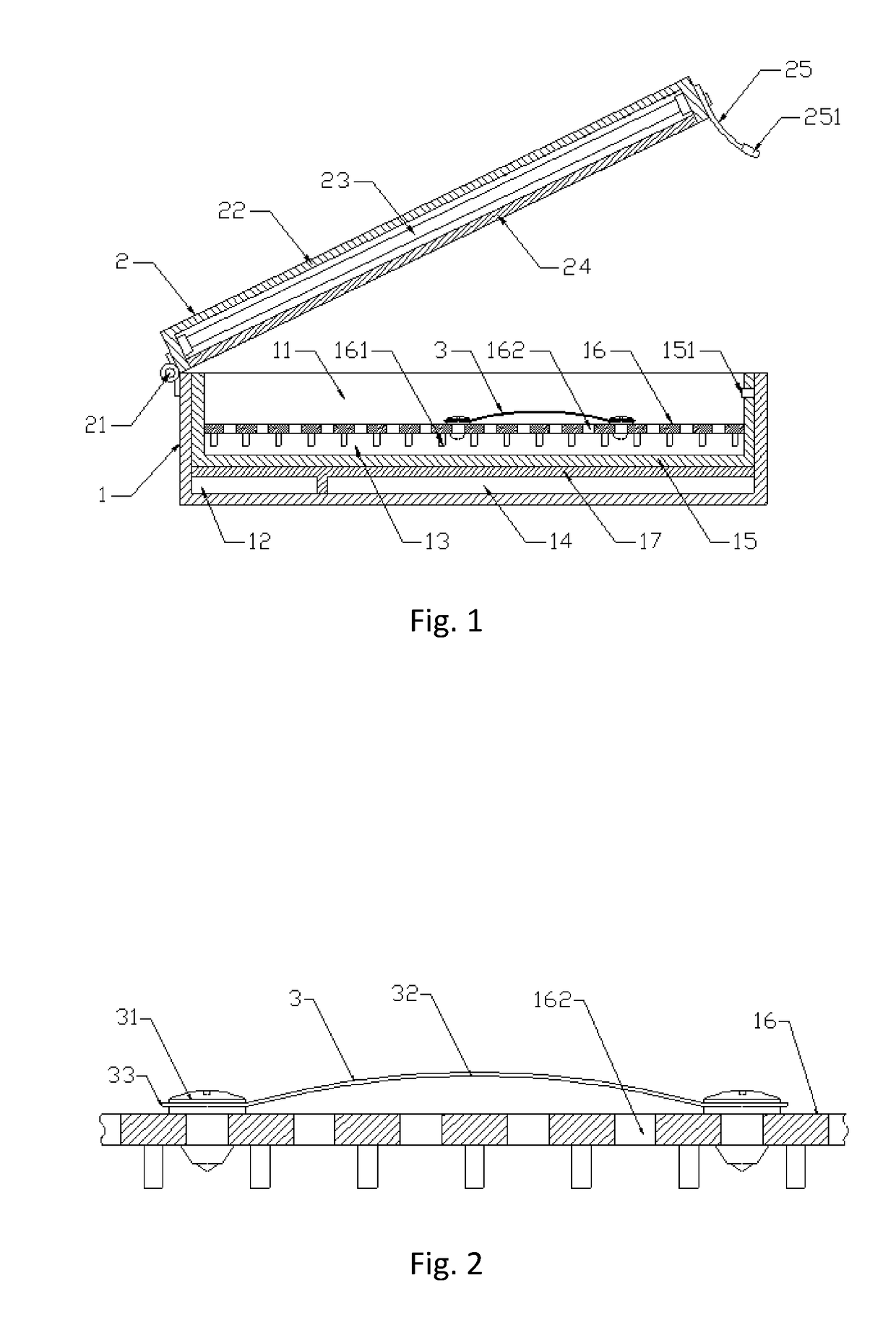
[0016]As shown in FIGS. 1-2, a preheated sterilizing box for medical laboratory equipment comprises a body 1, a cover 2 hinged to the body 1 through a hinge 21, and an attachment device 3 for preventing collision between preheated equipment. The cover 2 comprises a cover housing 22, a UV lamp 23 disposed on the cover and a transparent cover board 24.

[0017]A separator 17 and a heat guiding plate 16 is mounted inside the body. The body 1 is separated by the separator 17 and the heat guiding plate 16 into a first chamber 11 for holding preheated sterilizing equipment, a second chamber 12, a third chamber 13 and a fourth chamber 14. An insulating layer 15 is disposed on the inside wall of the first chamber ...


PUM


Abstract

The present invention relates to a preheated sterilizing box for medical laboratory equipment, comprising a body, a cover hinged to the body through a hinge, and an attachment device for preventing collision between preheated equipment. The cover comprises a cover housing, a UV lamp disposed on the cover and a transparent cover board. The body is separated by the separator and the heat guiding plate into a first chamber for holding preheated sterilizing equipment, a second chamber disposed with temperature control circuitry, a third chamber disposed with a heating material and a fourth chamber disposed with a battery. An insulating layer is disposed on the inside wall of the first chamber and the third chamber, a temperature sensor is embedded in the insulating layer disposed on the inside wall of the first chamber. A number of heat guiding poles and through holes are disposed on the heat guiding plate. The attachment device is disposed on the through holes. The sterilizing box has a sensible structure, having the advantages of simple, convenient to use, well portable, can effectively solve the problem of secondary contamination during preheating and sterilizing of medical laboratory equipment.

Description

FIELD OF INVENTION[0001]The present invention relates to the field of medical laboratory equipment, in particular to a preheated sterilizing box for medical laboratory equipment.BACKGROUND OF INVENTION[0002]Medical laboratory is a field of using modern physical and chemical methods and means for clinical diagnosis, mainly researching on how to provide bases for clinical diagnosis through laboratory technology and medical equipment. During operation of medical testing, sterilization and preheating of testing equipment to be used is usually needed. Normal sterilizing boxes and heating boxes are large and not portable, therefore the usual method is to first sterilize the equipment in the sterilizing box, and then move to the heating box for preheating. This is not only tedious but also testing equipment may also be contaminated when moving from sterilizing box to the heating box, leading to unnecessary troubles. Furthermore, fragile equipment may collide with each other and break durin...

Claims


Application Information

Patent Timeline
IPC IPC(8): A61L2/00A61L2/20A61L2/04A61L2/10
CPCA61L2/0047A61L2/20A61L2/0005A61L2/10A61L2/04A61L2/26B01L7/00A61L2202/11B01L2300/1805A61L2202/24
Inventor CHAN, KA YAN
Owner CHAN KA YAN
Why Eureka
Try Eureka