Vehicle front portion structure

a front portion and vehicle technology, applied in the direction of bumpers, pedestrian/occupant safety arrangements, instruments, etc., can solve the problems of inability to absorb collision energy, inability to reduce collision load amount, and increased so as to reduce the amount of collision load input to the collision body, the flexion change angle of the joint portion of the damage to the collision body can be further reduced.

Active Publication Date: 2018-10-11
TOYOTA JIDOSHA KK
View PDF6 Cites 11 Cited by
  • Summary
  • Abstract
  • Description
  • Claims
  • Application Information

AI Technical Summary

Benefits of technology

[0018]According to the aspect of the disclosure, the attachment position of the radar device can be appropriately adjusted (changed) and the transmission and reception of the radio waves can be performed further appropriately.
[0019]In the vehicle front portion structure disclosed in the specification, the collision energy is absorbed by the bumper absorber. The bumper cover, the front grill, and the radar device move rearward, and thus a collision reaction force is unlikely to be generated and a collision load amount input to the collision body can be further reduced. In addition, by the deformation limiting member being provided, the deformation of the front grill or the bumper cover to the radar device side is limited even when the collision body falls to the front grill or the bumper cover after the collision energy is consumed (after a retreat movement is completed), and thus the inclination amount of an upper portion of the collision body falling to the front grill and so on can be further reduced and the flexion change angle of a joint portion of the collision body can be further reduced.
[0020]As a result, damage to the collision body can be further reduced.

Problems solved by technology

Normally, the radar device described above is a rigid body, is unlikely to be crushed, and is not capable of absorbing collision energy.
As a result, the flexion change angle of the joint portion of the collision body may further increase and more damage may be done to the collision body.

Method used


Image

  • Vehicle front portion structure
  • Vehicle front portion structure
  • Vehicle front portion structure

Examples


Embodiment Construction

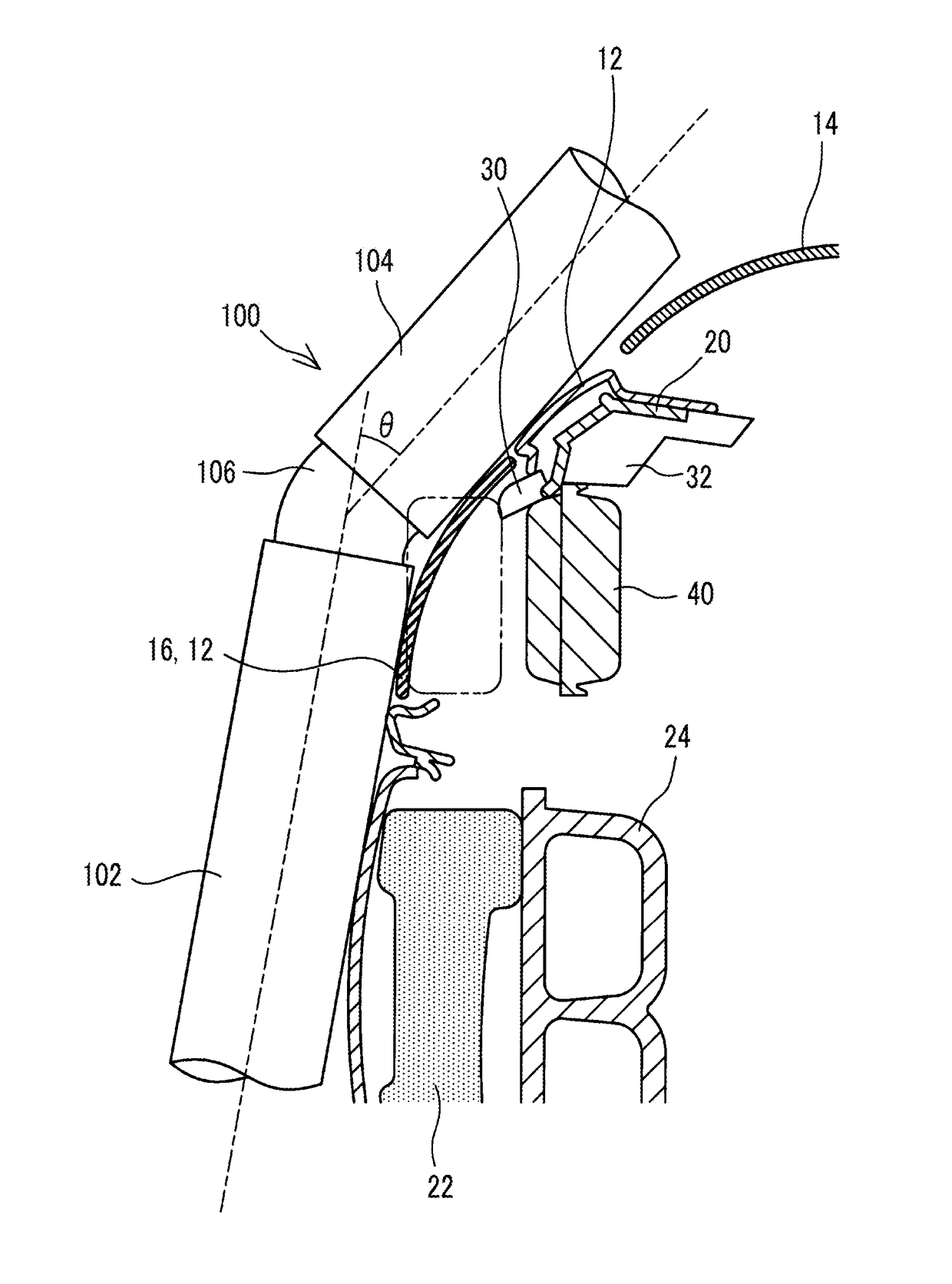
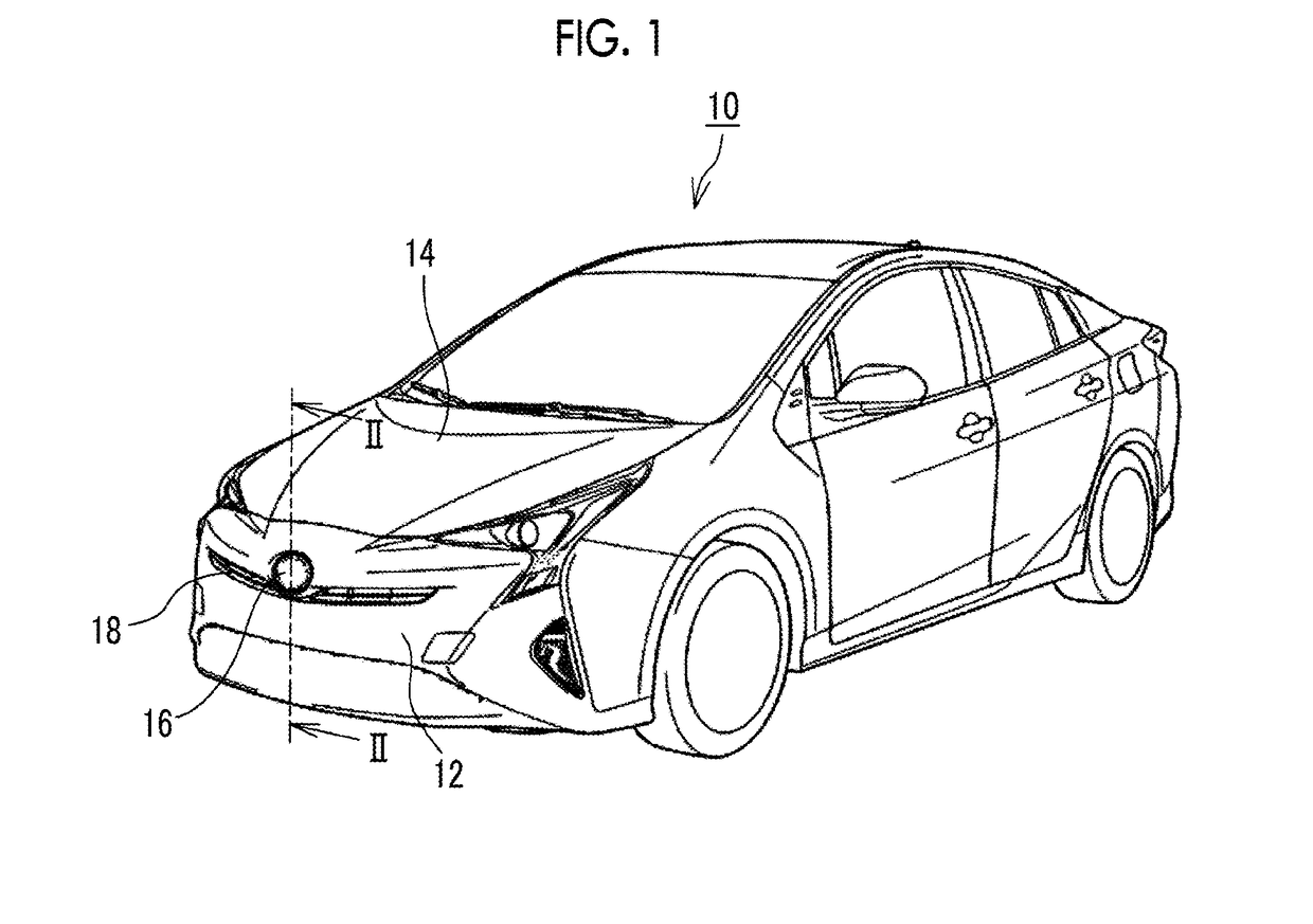
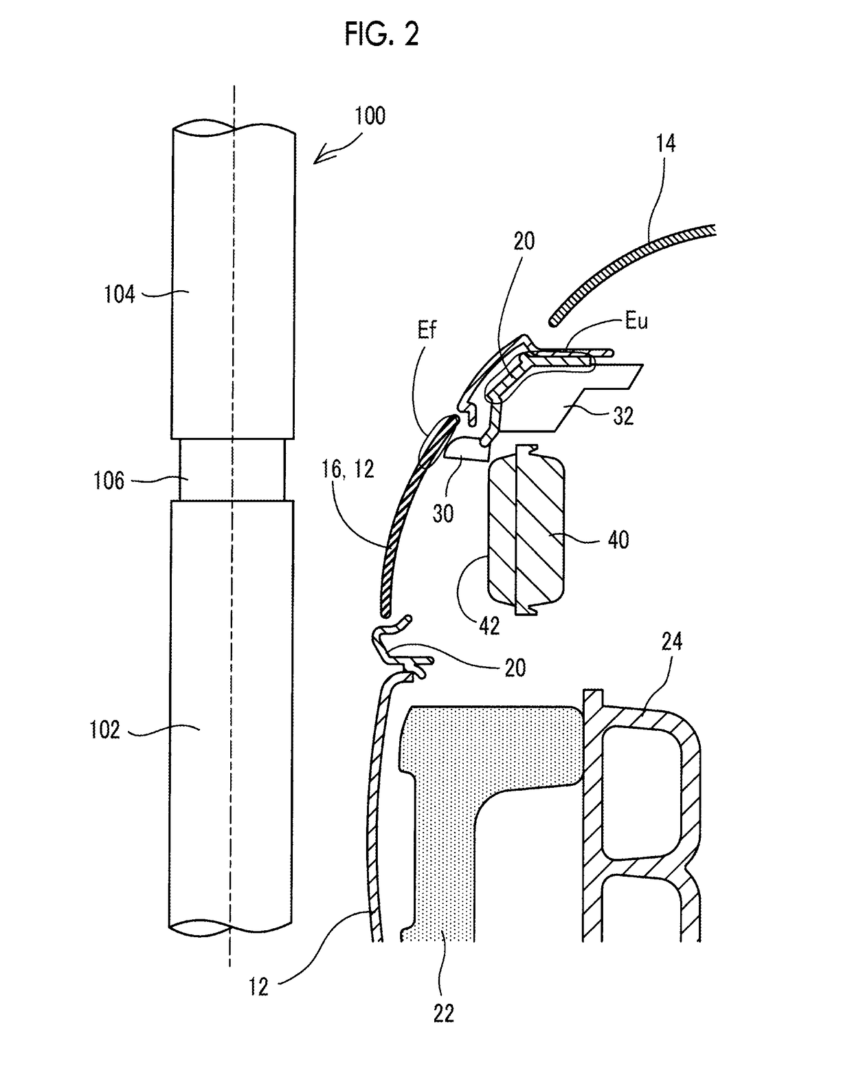
[0027]Hereinafter, a vehicle front portion structure will be described with reference to accompanying drawings. FIG. 1 is a perspective view in which a vehicle 10 is seen from the front. FIG. 2 is a midline sectional view of the vehicle front portion that is indicated by line II-II in FIG. 1. The front end surface of the vehicle 10 is covered with a bumper cover 12. A hood 14 is provided on the bumper cover 12 and an engine compartment is configured below the hood 14.

[0028]The bumper cover 12 is a thin-walled molded member formed of a resin member or the like. The bumper cover 12 can be deformed relatively easily. An air introduction port 18 elongated in a width direction is formed in the bumper cover 12. In addition, an emblem 16 is provided substantially in the middle of the air introduction port 18 in the width direction. A material allowing radio waves emitted from a radar device 40 (described later) to be transmitted, such as resin, constitutes the emblem 16.

[0029]A bumper rein...


PUM


Abstract

A vehicle front portion structure includes a cover; an absorber provided rearward of the cover of a vehicle, the absorber being configured to absorb energy of a collision between the cover and a collision body while allowing the cover to move rearward; a front grill provided rearward of the cover and above the absorber, the front grill being configured to move rearward along with the cover during the collision between the cover and the collision body; a radar device attached to the front grill; and a deformation limiting member provided outside a radio wave irradiation range of the radar device and in a space between the radar device and the front grill or the cover, the deformation limiting member being configured to limit deformation of the front grill or the cover to the radar device side during the collision between the cover and the collision body.

Description

INCORPORATION BY REFERENCE[0001]The disclosure of Japanese Patent Application No. 2017-076190 filed on Apr. 6, 2017 including the specification, drawings and abstract is incorporated herein by reference in its entirety.BACKGROUND1. Technical Field[0002]The specification discloses a vehicle front portion structure provided with a bumper cover, a bumper absorber and a front grill provided rearward of the bumper cover of a vehicle, and a radar device attached to the front grill.2. Description of Related Art[0003]Multiple techniques have been proposed in the related art for further reducing the damage that is done to a collision body (such as a pedestrian's leg) when the collision body collides with the front of a vehicle. Normally, the collision body has a lower portion and an upper portion interconnected upward and downward via a joint portion. A reduction in the amount of change in the flexion change angle of the joint portion of the collision body (angle formed by the lower portion ...

Claims


Application Information

Patent Timeline
Patent Type & Authority Applications(United States)
IPC IPC(8): B60R21/00B60R19/48B60R19/02G01S13/931
CPCB60R21/00B60R19/483B60R19/023B60R2021/0051B60R2019/525B60R19/52B60R21/34B60R2021/343B60R2019/527G01S13/931H01Q1/3233H01Q1/3283G01S2013/93271G01S7/027
Inventor IKENO, EISUKE
Owner TOYOTA JIDOSHA KK
Why Eureka
Try Eureka