Load control type exciter

A load control and exciter technology, applied in the direction of controlling mechanical energy, instruments, manufacturing tools, etc., can solve the problems of large initial load, workpiece damage, and initial load becoming larger.

Inactive Publication Date: 2005-06-08
MURATA MFG CO LTD
View PDF0 Cites 0 Cited by
  • Summary
  • Abstract
  • Description
  • Claims
  • Application Information

AI Technical Summary

Problems solved by technology

[0006] In the component assembly equipment with the suction nozzle 2, when there is no part to be sucked, or when the suction is not coordinated, air leakage occurs, and the suction force generated by the air is unbalanced with the initial load of the spring 22, so that the initial load becomes large. Damage to workpieces during processing
[0007] In addition, since the suction portion 21a is released when the workpiece W is to be picked up by suction, the initial load is not so large; 21a is closed, so the nozzle 21 is dragged towards the movable part 20, so that the initial load is greater
Therefore, there is a problem that the load applied to the workpiece W during placement is greater than that during pick-up

Method used


Image

  • Load control type exciter
  • Load control type exciter
  • Load control type exciter

Examples


Embodiment Construction

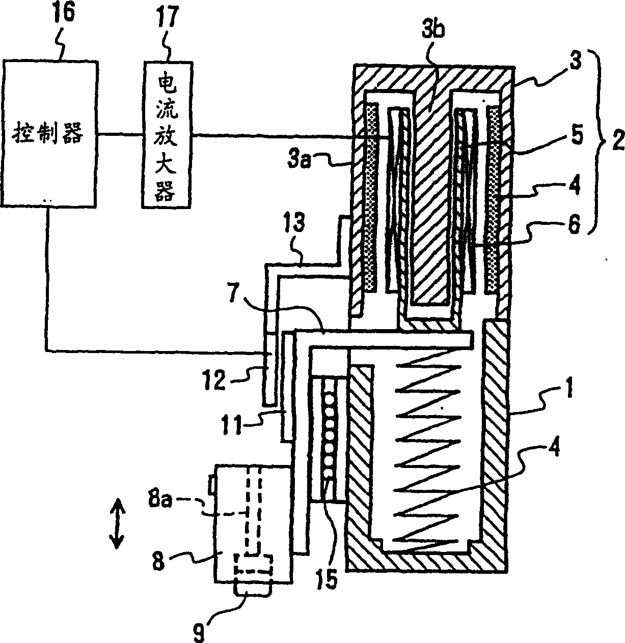
[0042]The processing device is made of non-magnetic material and mounted to the chassis 1 of the X-Y robot, and the magnetic circuit is set to the magnetic circuit of the voice coil motor. The magnetic circuit 2 includes a yoke 3 fixed to the upper portion of the chassis 1, a magnet 4 fixed to the inner surface of a cylindrical portion 3a of the yoke 3, a bobbin 5 vertically movable inserted by the center pole 3b of the yoke 3, and a winding Coil 6 of bobbin 5. The coil 6 overlaps the magnet 4 in the axial direction. In this embodiment, the magnet 4 is provided on the fixed side and the coil 6 is provided on the movable side; however, conversely, the coil 6 may be provided on the fixed side and the magnet 4 on the movable side.

[0043] On the lower end face of the bobbin 5, one end of the connecting member 7 is fixed, and the other end protrudes radially from the chassis 1 and the yoke 3, and a nozzle holder (movable member) 8 is fixed to its protruding portion 7a. Such as ...


PUM


Abstract

The present invention provides a load control type actuator in which the impact load applied to the workpiece is reduced, enabling less damage in the workpiece. The load-controlled actuator consists of: a nozzle in contact with the workpiece, a nozzle holder for supporting the nozzle by a spring, and a voice coil motor capable of controlling the driving thrust to the nozzle holder. The spring constant of the spring is set such that the spring reaction force of the spring within the response time of the voice coil motor is reduced to be smaller than the maximum impact load when the nozzle contacts the workpiece. Suspend and support the nozzle by a spring and set its initial load to 0.

Description

technical field [0001] The invention relates to a load-controlled actuator for use in processing equipment and in measuring and sorting equipment for measuring electrical characteristics of electronic components. Background technique [0002] Hitherto, when mounting small-sized electronic components on circuit boards, component mounting equipment using voice coil motors has been widely used. Compared to those mounters that utilize pneumatic power and solenoids, voice coil motors are excellent in positioning accuracy and also excellent in reducing the force applied to the component. [0003] figure 1 An example of a conventional processing device using such a voice coil motor is shown. The movable part 20 of the Z-axis driving mechanism is driven by the voice coil motor along the vertical direction. The nozzle 21 is provided at the lower end of the movable part 20 , and the built-in spring 22 is provided between the movable part 20 and the nozzle 21 . A suction port 21a i...

Claims


Application Information

Patent Timeline
Patent Type & Authority Patents(China)
IPC IPC(8): G01R31/00B25J19/00H02K7/00H02K33/18H02K41/035
CPCH02K41/0356B23P21/00
Inventor 福永茂树辻滋牧谦一郎
Owner MURATA MFG CO LTD
Why Eureka
Try Eureka