
Train Traffic Situation Display System

Active Publication Date: 2018-10-11
CHU SHU TONG +1
View PDF13 Cites 1 Cited by
  • Summary
  • Abstract
  • Description
  • Claims
  • Application Information

AI Technical Summary

Benefits of technology

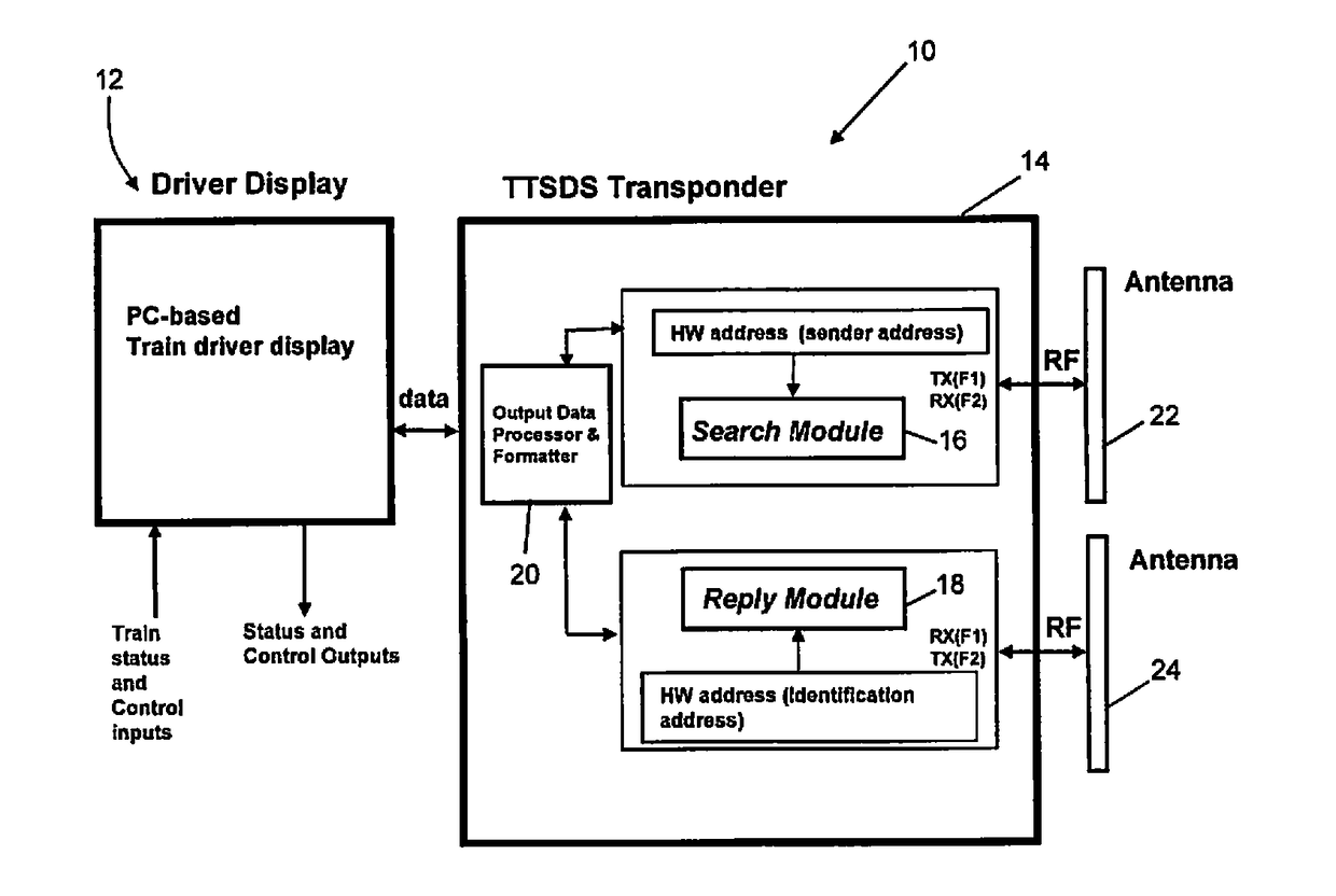
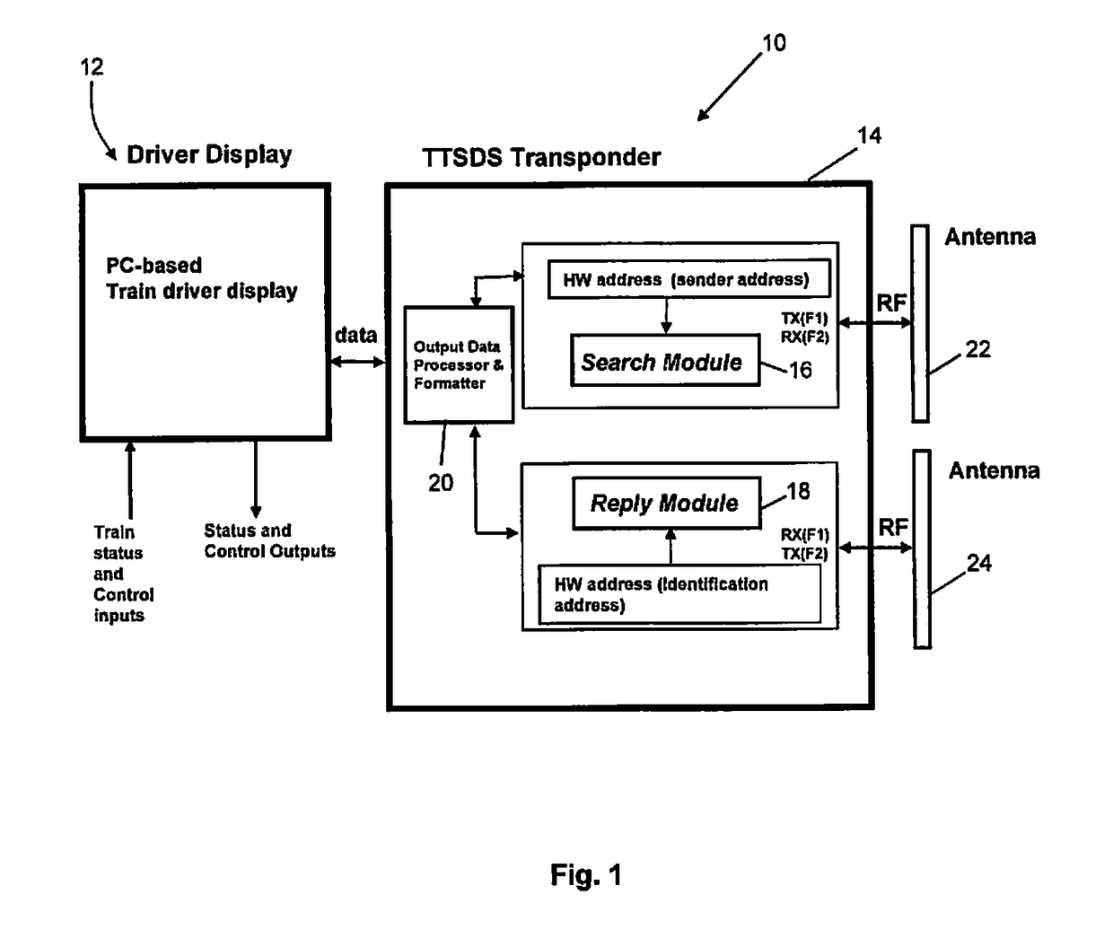
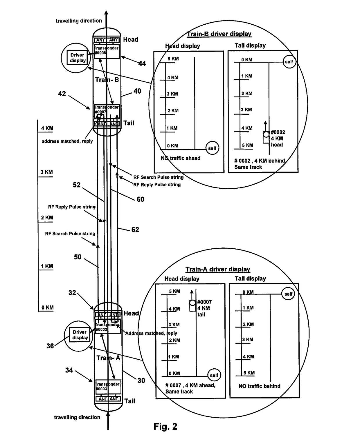
The patent describes a system that uses radio technology to detect and calculate the distance of an intended target. This system is designed to be a standalone backup system for train safety that can detect and prevent collisions with other trains. It works by measuring the time it takes for a search pulse to travel to the target and receive a valid reply pulse. By subtracting processing time and multiplying the result by the speed of radio waves, the distance to the target can be calculated. The system is easy to use and requires no external sensors or data, making it a practical solution for preventing collisions. The detection range is up to 10 kilometers, giving drivers enough time to react to critical situations.

Problems solved by technology

Despite the use of sophisticated safety systems including centrally controlled safety systems, train accidents continue to occur.
These sometimes occur as a result of local failures in the centrally controlled safety systems.
In February 2016, two commuter trains in southern Germany collided head-on in good weather resulting in at least ten dead.
In the same year, a similar head-on collision between two trains occurred in Ruvo di Puglia and Corato, Italy causing twenty deaths and dozens injured.
However, CN1325805 does not include calculating actual distances between trains and does not suggest enabling any transponder on any train to respond with a reply signal when it receives a transponder signal from another train.

Method used


Image

  • Train Traffic Situation Display System
  • Train Traffic Situation Display System
  • Train Traffic Situation Display System

Examples


Embodiment Construction

[0036]The following description is of preferred embodiments by way of example only and without limitation to the combination of features necessary for carrying the invention into effect.

[0037]Reference in this specification to “one embodiment” or “an embodiment” means that a particular feature, structure, or characteristic described in connection with the embodiment is included in at least one embodiment of the invention. The appearances of the phrase “in one embodiment” in various places in the specification are not necessarily all referring to the same embodiment, nor are separate or alternative embodiments mutually exclusive of other embodiments. Moreover, various features are described which may be exhibited by some embodiments and not by others. Similarly, various requirements are described which may be requirements for some embodiments but not other embodiments.

[0038]It should be understood that the elements shown in the FIGS, may be implemented in various forms of hardware, s...


PUM


Abstract

Provided is a method and system for determining a separation distance between a first object and a second object. It is envisaged that at least one of the objects is a movable vehicle such as a train. The method comprises using a search module associated with a first object where said search module comprises a first transponder having a unique address. The method includes using a reply module associated with a second object where said reply module comprises a second transponder having a different, unique address. The method includes the search module transmitting a search signal on a first frequency, said search signal including the address of the first transponder and the address of the second transponder. The reply module receives the search signal and locally validates the address included in said received search signal for the second transponder, whereby, if the validation is positive; the reply module transmits a reply signal on a second, different frequency, said reply signal including the address of the second transponder and the address of the first transponder. The search module receives the reply signal and locally validates the address included in said received reply signal for at least the second transponder whereby, if the validation is positive, the search module determines a separation distance between the first object and the second object based on a time taken from transmission of the search signal to receipt of the reply signal at said search module. The local validation of the address of the second transponder at the reply module and then at the search module improves reliability of processing of reply signals and allows the method to be implemented in a stand-alone configuration not reliant on signals from external systems.

Description

CROSS-REFERENCE TO RELATED APPLICATIONS[0001]This application claims priority to U.S. Provisional Application No. 62 / 484,079 filed Apr. 11, 2017 which is incorporated herein by reference.FIELD OF THE INVENTION[0002]The invention relates to a method and system for determining the position of a first object relative to a second object. The invention is more particularly related to a method and system for determining a position of a first vehicle such as a train with respect to the position(s) of one or more other vehicles in order to provide an operator / driver of a train with at least a traffic situation display.BACKGROUND OF THE INVENTION[0003]Despite the use of sophisticated safety systems including centrally controlled safety systems, train accidents continue to occur. These sometimes occur as a result of local failures in the centrally controlled safety systems. In February 2016, two commuter trains in southern Germany collided head-on in good weather resulting in at least ten dea...

Claims


Application Information

Patent Timeline
IPC IPC(8): B61L23/34B61L25/08B61L25/02G01S19/46
CPCB61L2205/04B61L25/023G01S19/46B61L25/08G01S2205/002B61L23/34B61L25/02B61L15/009B61L23/22G01S13/76G08G1/161G08G1/166G08G1/09623G08G1/0965G08G1/096708G08G1/096716G08G1/096725G08G1/123G08G1/133G08G1/137G08G1/163G08G1/20G08G1/22
Inventor CHU, SHU TONGZHOU, QUN
Owner CHU SHU TONG
Learn More