Damage information processing device and damage information processing method
- Summary
- Abstract
- Description
- Claims
- Application Information
AI Technical Summary
Benefits of technology
Problems solved by technology
Method used
Image
Examples
first embodiment
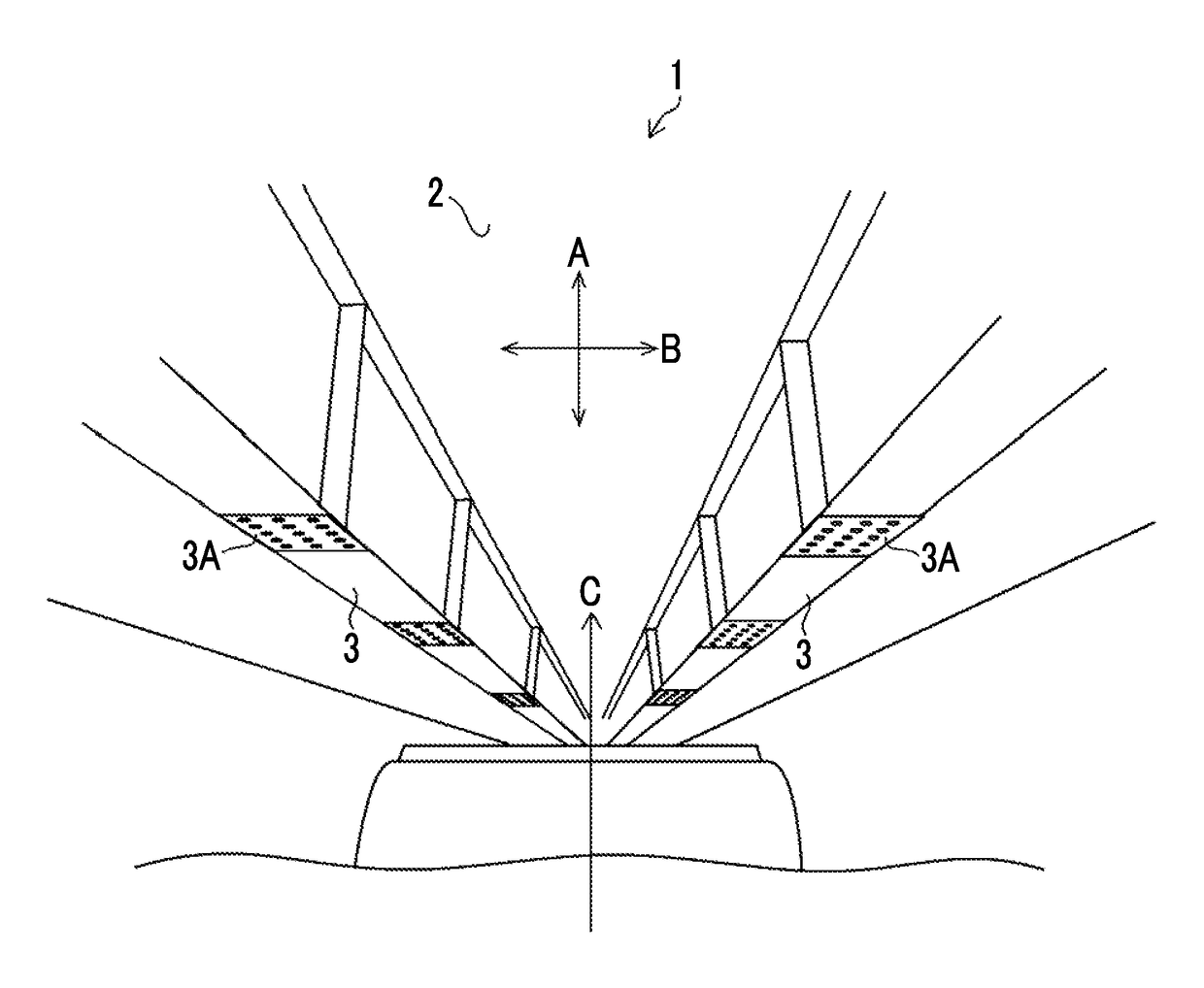
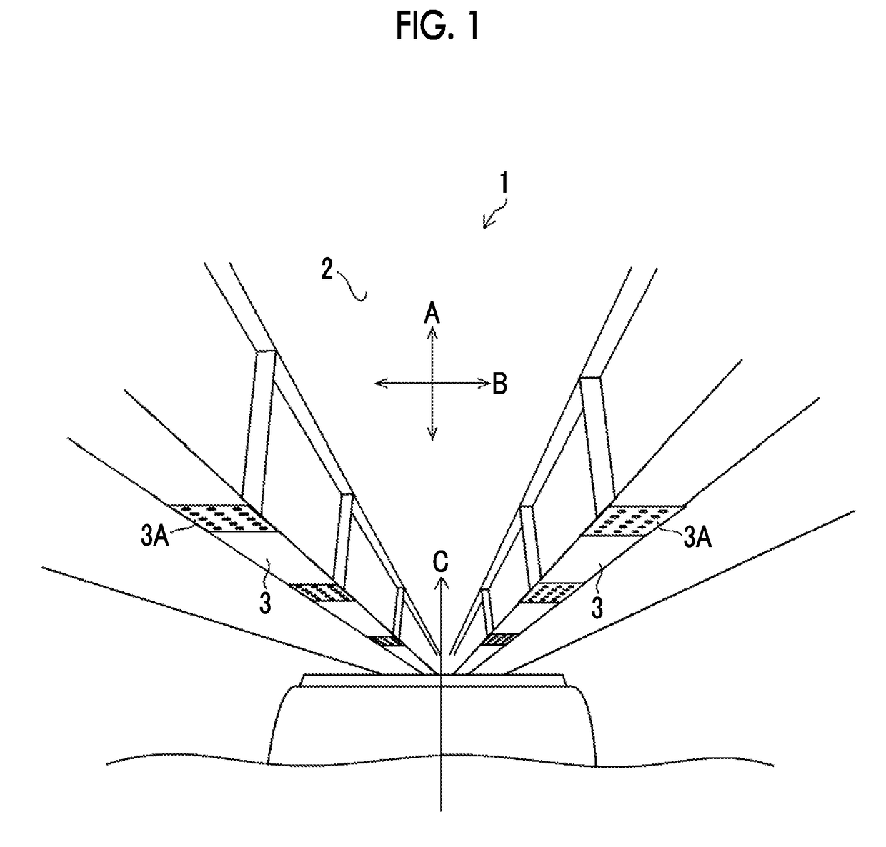
[0048]FIG. 1 is a perspective view illustrating a structure of a bridge 1 (a structure or a concrete structure) which is an example of a structure to which a damage information processing device and a damage information processing method according to the present invention are applied. The bridge 1 illustrated in FIG. 1 includes a main girder 3, and the main girder 3 is bonded to a joint 3A. The main girder 3 is a member that is passed between abutments or piers and supports a load of vehicles or the like on a deck 2. Further, the deck 2 on which vehicles travel is installed in an upper portion of the main girder 3. The deck 2 is assumed to be a deck made of general rebar concrete. It should be noted that the bridge 1 includes members such as a transverse girder, a sway bracing, and a lateral bracing (not illustrated), in addition to the deck 2 and the main girder 3.
Acquisition of Image
[0049]In a case where damage of the bridge 1 is inspected, an inspector images the bridge 1 from th...
example 1
Hierarchy Determination Scheme (Example 1)
[0074]FIG. 11 is a diagram illustrating the vector group C1. The vector group C1 includes damage vectors C1-1 to C1-6, and the damage vectors have points P1 to P7 as start points or termination points. Under such a situation, in Example 1, it is assumed that the hierarchy becomes lower each time the damage vector branches (a termination point of a certain damage vector is a start point of a plurality of other damage vectors). Specifically, the hierarchy of the damage vector C1-1 is set as the highest “level 1”, and a hierarchy of damage vectors C1-2 and C1-3 in which the point P2 serving as the termination point of the damage vector C1-1 is set as the start point is set to be at “level 2” which is lower than the damage vector C1-1. Similarly, a hierarchy of the damage vectors C1-5 and C1-6 in which point P4 which is the termination point of the damage vector C1-3 is set as a start point is set to be at “level 3” which is lower than the damag...
example 2
Hierarchy Determination Scheme (Example 2)
[0075]FIG. 12 is a diagram illustrating a vector group C1 (a connection relationship between damage vectors is the same as that illustrated in FIG. 11). In Example 2, it is assumed that one of the damage vectors to be connected of which an angle formed with respect to another damage vector is equal to or smaller than the threshold value (a damage vector corresponding to a “trunk” in a tree structure) belong to the same hierarchy. Specifically, damage vectors C1-1, C1-2, and C1-4 present within a dotted line (a range indicated by a reference symbol Lv1) in FIG. 12 are set to “level 1” (the highest level) which is the same hierarchy. Further, for other damage vectors C1-3, C1-5, and C1-6, the hierarchy becomes lowered each time the damage vector branches as in Example 1, the damage vector C1-3 (corresponding to a “branch” in a tree structure) is set to a “level 2”, and the damage vectors C1-5 and C1-6 (corresponding to “leaves” in the tree str...
PUM
 Abstract
Description
Claims
Application Information
 - R&D
- Intellectual Property
- Life Sciences
- Materials
- Tech Scout
- Unparalleled Data Quality
- Higher Quality Content
- 60% Fewer Hallucinations
Browse by: Latest US Patents, China's latest patents, Technical Efficacy Thesaurus, Application Domain, Technology Topic, Popular Technical Reports.
© 2025 PatSnap. All rights reserved.Legal|Privacy policy|Modern Slavery Act Transparency Statement|Sitemap|About US| Contact US: help@patsnap.com


