
Trajectory setting device and trajectory setting method

a technology of trajectory setting and setting device, which is applied in the direction of scene recognition, navigation instruments, instruments, etc., can solve the problems of inability to appropriately set the trajectory of the host vehicle for traveling from the path, the method set in advance in the control device and the like for generating paths may be inappropriate, and the host vehicle for traveling may not be appropriately set from the path

Active Publication Date: 2018-10-11
TOYOTA JIDOSHA KK
View PDF14 Cites 38 Cited by
  • Summary
  • Abstract
  • Description
  • Claims
  • Application Information

AI Technical Summary

Benefits of technology

The trajectory setting device and method described in this patent allow for the generation of multiple paths for a vehicle based on the presence of obstacles, and can appropriately set the vehicle's trajectory based on the reliability of each path. This means that the device and method can consider the reliability of sensing and prediction when calculating the paths, resulting in a more accurate and reliable trajectory for the vehicle. The technical effects of this invention include improved safety and efficiency in obstacle avoidance for autonomous vehicles, as well as improved reliability and accuracy in path planning for non-autonomous vehicles.

Problems solved by technology

However, the method set in advance in the control device and the like for generating paths may be inappropriate according to the situation of the host vehicle.
In such a case, all paths generated using the method are inappropriate, and the trajectory of the host vehicle for traveling may not be appropriately set from the paths.
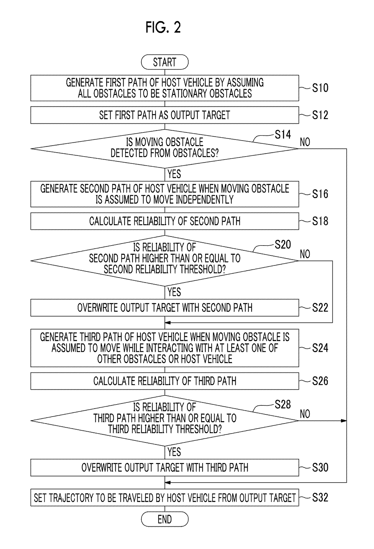
Thus, a situation where the trajectory of the host vehicle for traveling cannot be set due to the insufficient reliability of the second path and the insufficient reliability of the third path is suppressed.

Method used


Image

  • Trajectory setting device and trajectory setting method
  • Trajectory setting device and trajectory setting method
  • Trajectory setting device and trajectory setting method

Examples


Embodiment Construction

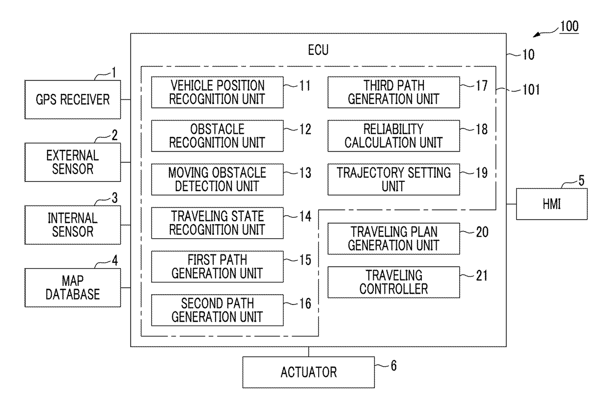
[0024]Hereinafter, an embodiment of the present disclosure will be described with reference to the drawings. A trajectory setting device according to the present embodiment constitutes a part of an autonomous driving system.

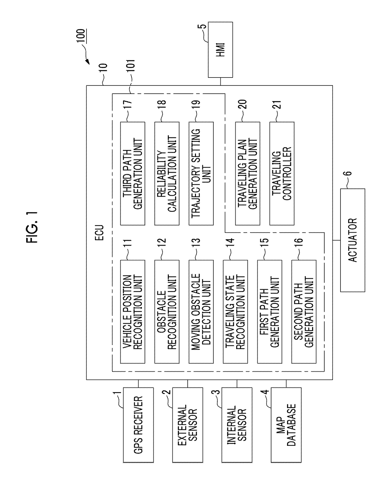
[0025]FIG. 1 is a diagram illustrating the autonomous driving system according to the present embodiment. An autonomous driving system 100 illustrated in FIG. 1 executes autonomous driving of a vehicle such as a passenger car. The autonomous driving is a vehicle control for the vehicle to autonomously travel toward a destination set in advance. The destination may be set by an occupant such as a driver, or may be automatically set by the autonomous driving system 100. In autonomous driving, the vehicle autonomously travels, and the driver does not need to perform a driving operation. Hereinafter, the vehicle that is a target for autonomous driving in the autonomous driving system 100 will be referred to as a host vehicle.

[0026]Configuration of Autonomous Driving ...


PUM


Abstract

A trajectory setting device that sets a trajectory of a host vehicle includes a first path generation unit configured to generate a first path by assuming all obstacles around the host vehicle to be stationary obstacles, a second path generation unit configured to generate a second path when the moving obstacle is assumed to move independently, a third path generation unit configured to generate a third path when the moving obstacle is assumed to move while interacting with at least one of the other obstacles or the host vehicle, a reliability calculation unit configured to calculate reliability of the second path and reliability of the third path, and a trajectory setting unit configured to set the trajectory for traveling from the first path, the second path, and the third path based on the reliability of the second path and the reliability of the third path.

Description

INCORPORATION BY REFERENCE[0001]The disclosure of Japanese Patent Application No. 2017-076069 filed on Apr. 6, 2017 including the specification, drawings and abstract is incorporated herein by reference in its entirety.BACKGROUND1. Technical Field[0002]The present disclosure relates to a trajectory setting device and a trajectory setting method.2. Description of Related Art[0003]For example, Japanese Unexamined Patent Application Publication No. 11-91397 (JP 11-91397 A) is known in the related art for a device that performs autonomous driving of a host vehicle. An autonomous traveling vehicle control device disclosed in JP 11-91397 A performs autonomous driving (autonomous traveling) of the host vehicle based on the result of detection of an external environment of the host vehicle.SUMMARY[0004]In order to perform autonomous driving of a host vehicle, candidates for possible paths of the host vehicle need to be generated using a method that is set in advance in a control device and ...

Claims


Application Information

Patent Timeline
Patent Type & Authority Applications(United States)
IPC IPC(8): G05D1/02G06K9/00G05D1/00G01C21/34
CPCG05D1/0214G06K9/00805G05D1/0088G01C21/3415G05D1/0257G05D1/0253G05D1/0217G01C21/20B60W30/10B60W50/0097B60W50/08B60W50/14B60W50/082B60W2554/00B60W60/0053G06V20/58B60W30/00B60W40/107B60W2520/28B60W2520/125B60W2520/105B60W2520/14B60W2420/403B60W2552/50B60W60/0027B60W60/0011B60W2554/406B60W2554/20B60W2554/4026B60W2554/4029B60W2420/408G05D1/247G05D1/243
Inventor KINDO, TOSHIKI
Owner TOYOTA JIDOSHA KK
Learn More