Breathing circuits to facilitate the measurement of cardiac output during controlled and spontaneous ventilation

a breathing circuit and cardiac output technology, applied in the field of breathing circuits to facilitate the measurement of cardiac output during controlled and spontaneous ventilation, can solve the problems of mechanical ventilation patients, and achieve the effect of easier and more precise volume control

Inactive Publication Date: 2018-10-18
THORNHILL SCI INC
View PDF1 Cites 4 Cited by
  • Summary
  • Abstract
  • Description
  • Claims
  • Application Information

AI Technical Summary

Benefits of technology

[0003]It is a primary object of this invention to provide circuits which will allow for easier and more precise control of the volume of absorption or elimination of CO2 or any other gas such as O2 or anesthetic vapor, from or to the lung respectively in both spontaneously breathing and mechanically ventilated patients.

Problems solved by technology

The main limitation of the breathing circuits and methods proposed by Gedeon and Orr is that they can only be used in mechanically ventilated patients, as ventilated patients will increase their breath size or breathing frequency to compensate for the reduction in ventilation induced by inhaling the rebreathed gas.

Method used


Image

  • Breathing circuits to facilitate the measurement of cardiac output during controlled and spontaneous ventilation
  • Breathing circuits to facilitate the measurement of cardiac output during controlled and spontaneous ventilation
  • Breathing circuits to facilitate the measurement of cardiac output during controlled and spontaneous ventilation

Examples


Embodiment Construction

[0042]Description of Circuit with Valves and Reservoirs Distal From Patient, and Precludes the Contamination of FGS with SGS Through Bypass Valve

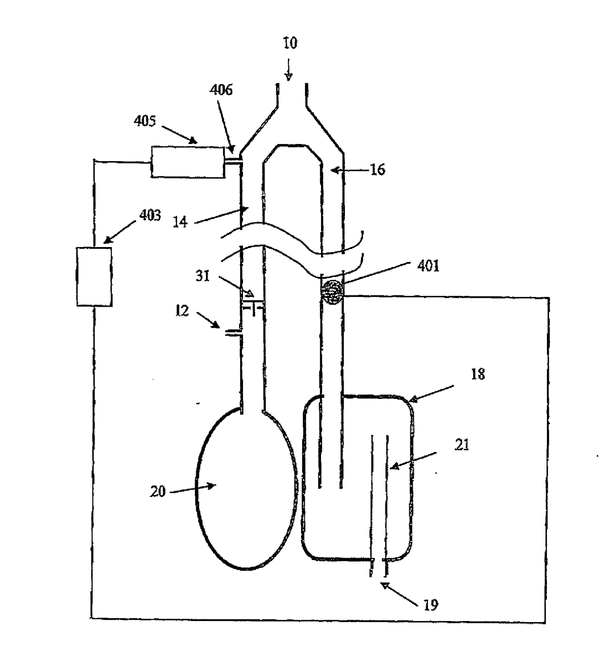
[0043]FIG. 5 shows a breathing circuit which provides sequential delivery of the FGS followed by the SGS when {dot over (V)}E exceeds FGSF, with the manifold containing the valves and the FGS reservoir bag and the expiratory gas reservoir bag remote from the patient. This improvement reduces the bulk of the patient manifold, and eliminates the possibility of the SGS mixing with the FGS due to vigorous exhalation.

[0044]Referring to FIG. 5, Patient (38) breathes via a Y connector (40). Valve (31) is an inspiratory valve and valve (33) is an expiratory valve. Valve (35) is a bypass valve in the bypass limb (34) that bypasses the expiratory valve (33) and has an opening pressure greater than inspiratory valve (31). Valves (35, 33) may be close to or distal from the patient manifold as desired, as long as they are on the expiratory limb (39). Ho...


PUM


Abstract

A breathing circuit for use with a first gas set (FGS) and a second gas set (SGS), said circuit comprising means for keeping separate the FGS and SGS, and a means for sequentially delivering to a patient, first the FGS, and, on inspiration, when the patient inspires so as to deplete the supply of FGS into the circuit, subsequently delivers substantially SGS for the balance of inspiration.

Description

BACKGROUND OF THE INVENTION AND PRIOR ART[0001]It is desirous to have an apparatus capable of measuring cardiac output in a non-invasive way. Several breathing circuits have been employed in the non-invasive measurement of cardiac output ({dot over (Q)}). For example, Gedeon in 1980 described a method of calculating {dot over (Q)} in ventilated patients using the equationQ.=V.CO2-V.CO2′PETCO2′-PETCO2[0002]where PETCO2 and PETCO2′ are the end tidal PCO2 resulting from a change in CO2 elimination from the lung ({dot over (V)}CO2) from {dot over (V)}CO2 to {dot over (V)}CO2′ respectively. To perform the method, a breathing circuit is required that can impose a step change in CO2 elimination in the lungs. The change in {dot over (V)}CO2 is sustained for about one blood recirculation time, or about 30 s. Orr et al. reduced lung CO2 elimination by using a breathing circuit where a dead space is temporarily interposed between the ventilator and the patient's airway resulting in a transient...

Claims


Application Information

Patent Timeline
Patent Type & Authority Applications(United States)
IPC IPC(8): A61B5/00A61B5/083A61M16/20A61B5/029A61M16/08A61M16/00A61M16/22
CPCA61M16/205A61M16/202A61M16/208A61M16/0858A61M2016/0027A61M16/206A61B5/029A61M16/22A61M16/08A61M16/0078A61B5/4821A61B5/0836A61B5/083A61M16/0833A61M16/0891A61B5/4836
Inventor FISHER, JOSEPHPRISMAN, EITANAZAMI, TAKAFUMIPREISS, DAVIDVESELY, ALEXSOMOGYI, RONADAMS, TEHILLANAYOT, DANISCOE, STEVE
Owner THORNHILL SCI INC
Why Eureka
Try Eureka