
Packer Backup Ring with Closed Extrusion Gaps

Inactive Publication Date: 2018-10-18
BAKER HUGHES INC
View PDF2 Cites 12 Cited by
  • Summary
  • Abstract
  • Description
  • Claims
  • Application Information

AI Technical Summary

Benefits of technology

The patent describes a design for a backup ring that has alternating L-shaped side slots that are offset and extend from the inside and outside of the ring. These slots are connected by an oval-shaped opening that increases in size as the slots are separated or a barrier is placed to prevent extrusion of the adjacent sealing element during ring expansion. The technical effect of this design is improved sealing efficiency and better control over the expansion of the ring.

Problems solved by technology

However, typical elastomeric seals maintain the tendency to extrude through even the smallest gaps in an anti-extrusion backup system.
Movement of the packers can cause them to leak and lose seal.
However, without anchors, movement from the base pipe tubing can further energize the elastomeric seal.
Energizing the seal from tube movement tends to overstress the near wellbore as well, leading to additional overstressing of the wellbore, allowing communication around the packer, loss of production, and potential loss of well control to surface.

Method used


Image

  • Packer Backup Ring with Closed Extrusion Gaps
  • Packer Backup Ring with Closed Extrusion Gaps
  • Packer Backup Ring with Closed Extrusion Gaps

Examples


Embodiment Construction

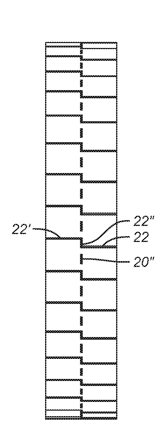
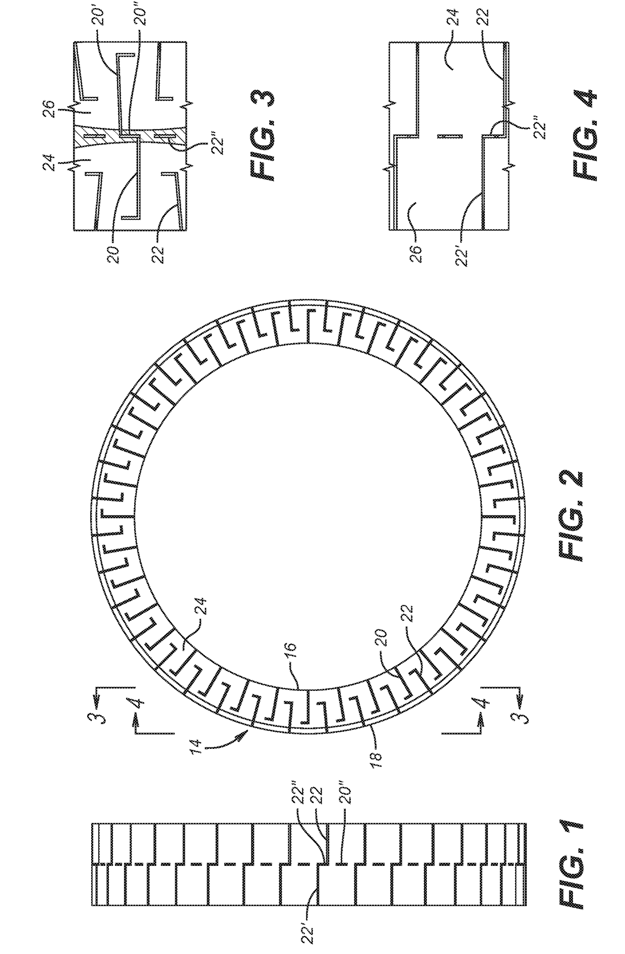
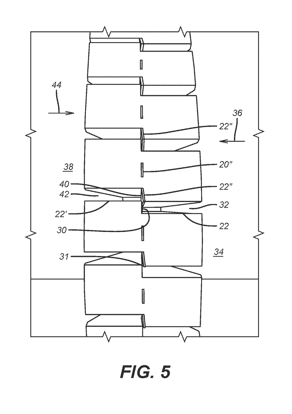
[0029]FIGS. 10 and 11 illustrate the juxtaposition of a sealing element 10 next to a backup ring 12. FIG. 2 shows an end view of a continuous single ring 14 that can be disposed next to a sealing element 10. Ring 14 has an inside diameter 16 and an outside diameter 18. There are alternating l-shaped slots 20 and 22 that start at the outside diameter 18 and at the inside diameter 16. FIG. 2 shows a tapered or sloping side 24 and slots 20 and 22 that alternate as to the location of the long dimension of the l-shaped slot. Sloping side 26 is not seen in FIG. 2 but is shown as FIG. 3 as well as the cylindrically shaped inside surface 28 that defines the inside diameter 16. FIGS. 1 and 4 both show an outside view where it is seen that slot 22 is a segment that goes to outside diameter 18 has a continuation slot segment 22′ that is circumferentially offset a few degrees. Slots 22 and 22′ are at opposed ends of an oblong bore 22″ that may have internal supports. Bore or opening 22″ is seen...


PUM


Abstract

Alternating l-shaped side slots are cut into opposed sides of a backup ring and are circumferentially offset and alternately extend from the inside and outside dimension. An oval shaped opening connects adjacent circumferentially offset slots so that on ring expansion the inside and outside diameters increase as the openings are sheared at one end to place a barrier in opened side slot to prevent extrusion of the adjacent sealing element.

Description

FIELD OF THE INVENTION[0001]The field of the invention is sealing systems for subterranean tools against tubular or open hole or cased hole and more particularly anti-extrusion barriers for low, medium and extended reach for a seal element.BACKGROUND OF THE INVENTION[0002]In the unconventional drilling and completion industry, oil and gas deposits are often produced from tight reservoir formations through the use of fracturing and frack packing methods. To frack a well involves the high pressure and high velocity introduction of water and particulate media, typically a sand or proppant, into the near wellbore to create flow paths or conduits for the trapped deposits to flow to surface, the sand or proppant holding the earthen conduits open. Often, wells have multiples of these production zones. Within each production zone it is often desirable to have multiple frack zones. For these operations, it is necessary to provide a seal known as a frack packer, between the outer surface of a...

Claims


Application Information

Patent Timeline
IPC IPC(8): E21B33/12E21B33/129E21B33/128
CPCE21B33/1216E21B33/128E21B33/1293
Inventor CAYSON, ANDREW J.KENDALL, ALEXANDER M.DENG, GUIJUN
Owner BAKER HUGHES INC
Learn More