Contouring a blade/vane cascade stage

a technology of blade/vane cascade and blade/vane channel, which is applied in the direction of machines/engines, climate sustainability, sustainable transportation, etc., can solve the problems of consuming and pressure losses, and achieve the effect of further reducing secondary flows

Active Publication Date: 2018-10-18
MTU AERO ENGINES GMBH
View PDF0 Cites 6 Cited by
  • Summary
  • Abstract
  • Description
  • Claims
  • Application Information

AI Technical Summary

Benefits of technology

[0013]The object of the present invention is to provide a technique with which secondary flows can be further reduced in an advantageous way in the annular space of a turbomachine.

Problems solved by technology

Thus, a secondary flow that is superimposed on an axial principal flow arises and, in particular, leads to vortexes and pressure losses.

Method used


Image

  • Contouring a blade/vane cascade stage
  • Contouring a blade/vane cascade stage

Examples


Embodiment Construction

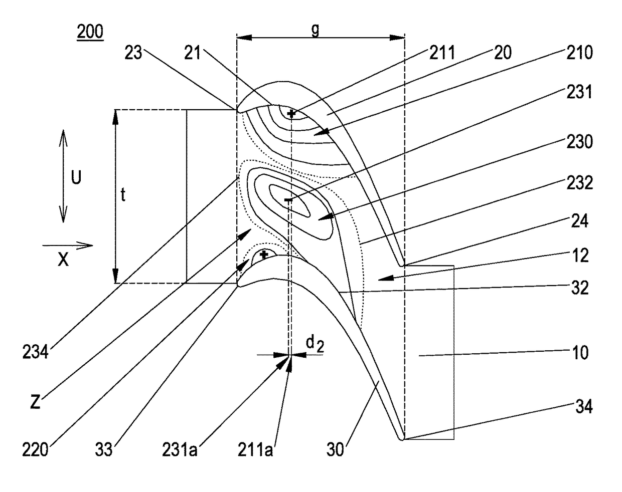
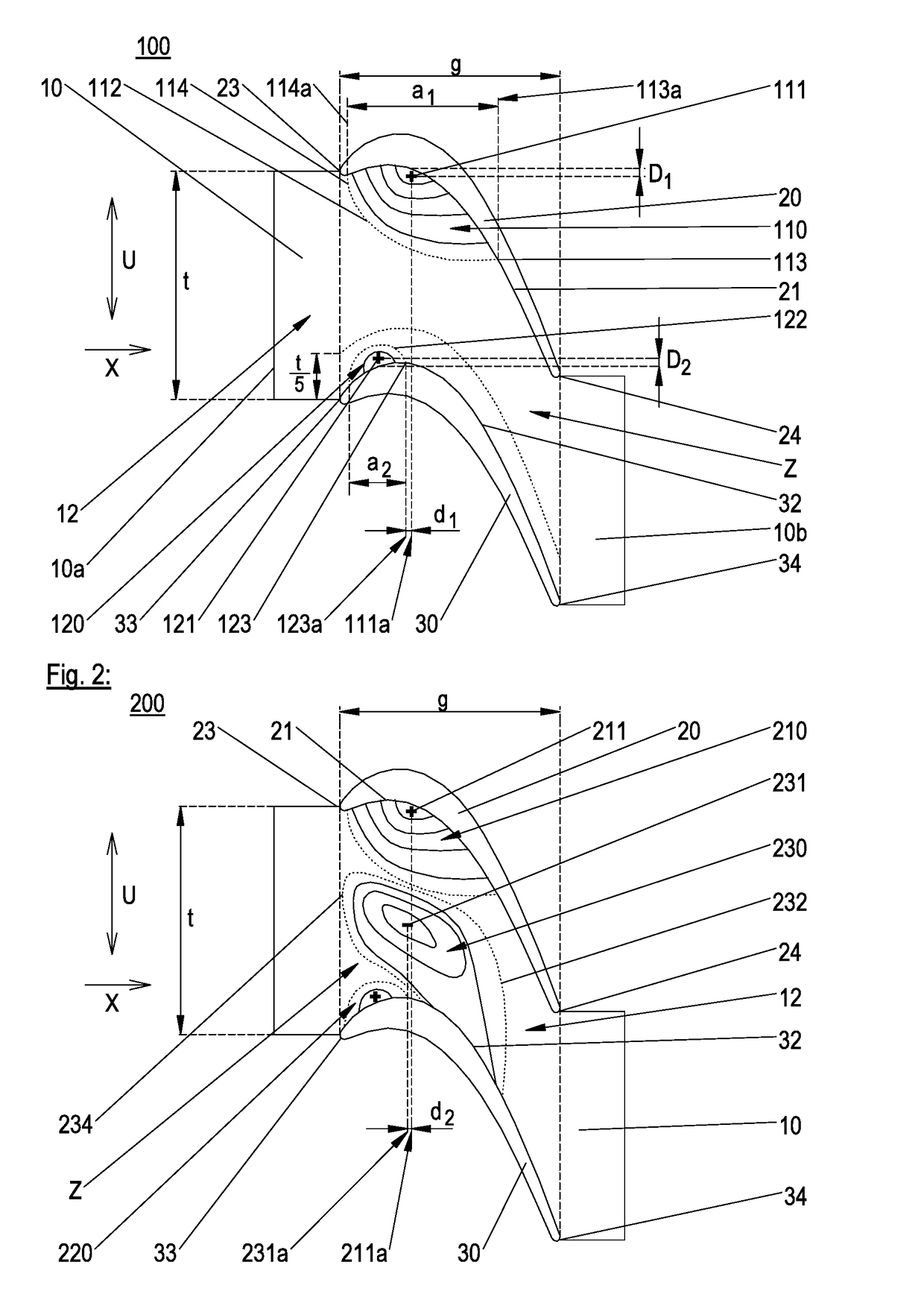
[0048]An exemplary, unrolled embodiment of a blade / vane cascade segment 100 according to the invention is shown schematically in FIG. 1 in top view (with radial direction of view). It comprises blade / vane elements 20, 30, each of which has a pressure side and a suction side, as well as a stage 10 according to the invention, with a stage surface 12, a stage edge 10a on the inflow side and a stage edge 10b on the outflow side (relative to the provided principal flow direction X). The stage can be designed as one part or, for example, it can be made of two parts (not shown); in particular, it can comprise two parts, from each of which projects one of the blade / vane elements 20, 30.

[0049]The blade / vane elements define a blade / vane intermediate strip Z as the surface section situated in the peripheral direction U between the pressure side 21 of the first blade / vane element 20 and the suction side 32 of the second blade / vane element 30 and bound in the axial direction X on the inflow side...


PUM


Abstract

A blade/vane cascade segment of a blade/vane cascade for a turbomachine is disclosed, which comprises a stage with a stage surface as well as a first blade/vane element and a second blade/vane element. The stage surface comprises a first elevation reaching as far as the pressure side of the first blade/vane element and a second elevation reaching as far as the suction side of the second blade/vane element. A furthest downstream point of a boundary of the second elevation has an axial position which differs from the axial position of at least one highest point of the first elevation by a maximum of 10% of an axial cascade span. Furthermore, a blade/vane cascade, a blade/vane channel, a stage, a turbomachine and an aircraft engine are disclosed.

Description

BACKGROUND OF THE INVENTION[0001]The present invention relates to a blade / vane cascade segment, a blade / vane cascade, a stage, and a blade / vane channel of a turbomachine, as well as a turbomachine.[0002]Turbomachines (such as gas and steam turbines) generally have a flow channel for conducting a fluid. The flow channel, which is also called an “annular space”, is bounded radially inward by the shaft of a rotor and radially outward by a casing; the designations “radially” as well as “axially” and “peripheral direction”, and terms derived therefrom are to be understood with reference to an axis of rotation of the rotor in this document, as long as nothing is indicated to the contrary.[0003]Blade / vane cascades (for which the term “blade / vane ring” is also common) are arranged in the annular space of a turbomachine. They each comprise guide vanes or rotating blades that lie one behind the other in the peripheral direction at substantially regular distances, as well as stages belonging t...

Claims


Application Information

Patent Timeline
Patent Type & Authority Applications(United States)
IPC IPC(8): F01D5/14F01D9/04
CPCF01D5/145F01D9/041F05D2220/30F05D2240/129F01D5/143F01D9/04F05D2240/11F05D2240/80Y02T50/60
Inventor BRETTSCHNEIDER, MARKUSMAHLE, INGAMAATOUK, FADI
Owner MTU AERO ENGINES GMBH
Why Eureka
Try Eureka