A fuel valve for a large two-stroke self-igniting internal combustion engine

a fuel valve and internal combustion engine technology, which is applied in the direction of engines, machines/engines, charge feed systems, etc., can solve the problems of less than optimal combustion of fuel, high combustion pressure of a large two-stroke self-igniting turbocharged internal combustion engine, and high fuel supply pressure, so as to increase the effective pressure and reduce the closing pressure

Active Publication Date: 2018-10-18
MAN ENERGY SOLUTIONS FILIAL AF MAN ENERGY SOLUTIONS SE TYSKLAND
View PDF2 Cites 0 Cited by
  • Summary
  • Abstract
  • Description
  • Claims
  • Application Information

AI Technical Summary

Benefits of technology

[0019]By providing the third effective pressure surface that assists the resilient biasing means in urging the valve needle towards the valve seat, it becomes possible to compensate completely or partially for the fact that the effective pressure surface that creates a force under the influence of pressurized fuel urge the valve member away from the valve seat is significantly increased from the moment that the valve needle has lift from the valve seat. Thus, the negative effect of the increased effective pressure surface that results in a lower closing pressure than opening pressure can be partially or completely removed. Consequently, it is possible to design a fuel valve with a closing pressure that is equal to the opening pressure or only slightly lower than the opening pressure. With such a design, the injection pressure can be kept high throughout the injection event, ensuring proper injection of the fuel into the combustion chamber throughout an injection event.

Problems solved by technology

The maximum combustion pressure of a large two-stroke self-igniting turbocharged internal combustion engine is very high, e.g. 200 bar and it is therefore difficult under an injection event to provide fuel at a pressure that is significantly higher than the combustion pressure.
The resulting low-pressure at the end of the injection event can result in the fuel not being injected with sufficient pressure through the nozzle holes, thereby resulting in less than optimal combustion for the fuel that is injected during the last part of the injection event.

Method used


Image

  • A fuel valve for a large two-stroke self-igniting internal combustion engine
  • A fuel valve for a large two-stroke self-igniting internal combustion engine
  • A fuel valve for a large two-stroke self-igniting internal combustion engine

Examples


Embodiment Construction

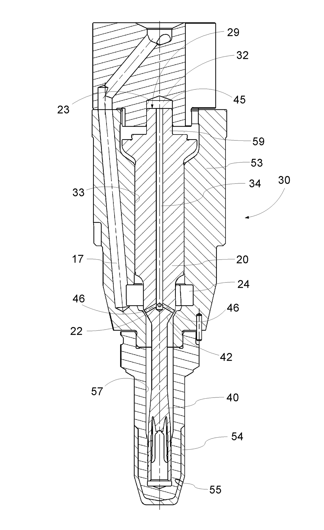
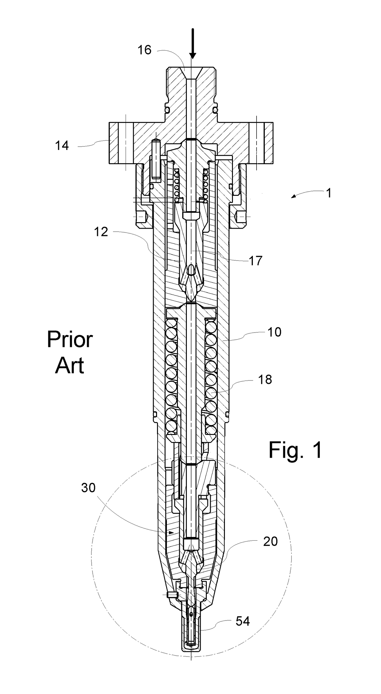
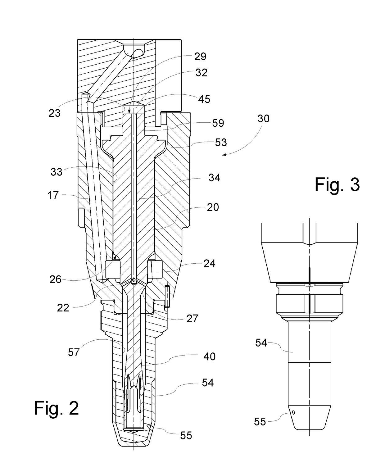
[0043]FIG. 1 illustrates a known fuel valve 1 for injecting fuel, such as e.g. fuel oil or heavy fuel oil or similar fuel into the combustion chamber of a large two-stroke self-igniting internal engine combustion engine. The fuel valve 1 illustrated in FIG. 1 has an elongated housing 10 which at its rearmost end has a head by which the fuel valve 1 in a known manner using bolts may be secured to the cylinder cover of a large two stroke diesel engine and be connected with a fuel pump (not shown). The head 14 includes a fuel oil inlet 16 which is in flow connection with a duct 17. The duct 17 extends through a non-return valve 12 to a valve needle axially displaceable in the valve housing 10. The valve needle 20 is biased to its seat 22 by a closing spring 18, such as e.g. a helical wire spring. The front end of the valve housing 10 holds a hollow nozzle 54 with a preferably closed tip that projects through the valve housing 10 and into the combustion chamber of the engine cylinder (n...


PUM


Abstract

A fuel valve for injecting fuel into the combustion chamber of a large two-stroke self-igniting internal engine combustion engine, with a valve needle that is resiliently biased towards a valve seat. The effective pressure surface that causes fuel pressure to urge the valve needle in the opening direction increases significantly when the valve needle has lift from the valve seat. A supplementary effective pressure surface is provided on the valve needle. The supplementary effective pressure surface creates a force urging the valve needle towards the valve seat when the supplementary effective pressure surface is exposed to fuel pressure.

Description

[0001]The present disclosure relates to a fuel valve for large two-stroke self-igniting internal combustion engines, in particular to a fuel valve for injecting fuel oil into the combustion chamber of a large turbocharged two-stroke uniflow internal combustion engine with crossheads.BACKGROUND[0002]Large two-stroke internal combustion engines are typically used as prime movers in large ocean going ships, such as container ships or in power plants.[0003]These engines are typically provided with two or three fuel valves arranged in each cylinder cover. A conventional fuel valve, as shown in FIG. 1, has a longitudinal axis that is arranged roughly at an angle of 10 to 15 deg to the direction of the movement of the piston in the cylinder of the engine. The fuel valve is provided with a nozzle at its front end that projects into the combustion chamber. The nozzle is provided with axial bore and a plurality of nozzle holes that direct the fuel away from the cylinder walls and into the com...

Claims


Application Information

Patent Timeline
Patent Type & Authority Applications(United States)
IPC IPC(8): F02M61/10F02M63/00
CPCF02M61/10F02M63/0005F02M49/00F02M61/20F02M63/04F02M61/205
Inventor FLARUP, JOHANNES
Owner MAN ENERGY SOLUTIONS FILIAL AF MAN ENERGY SOLUTIONS SE TYSKLAND
Why Eureka
Try Eureka