
Lens Module

Active Publication Date: 2018-10-18
AAC OPTICS SOLUTIONS PTE LTD
View PDF2 Cites 1 Cited by
  • Summary
  • Abstract
  • Description
  • Claims
  • Application Information

AI Technical Summary

Benefits of technology

The patent text describes a lens module with a third surface that is designed to reduce stray light and improve imaging quality. The third surface is a circular arc curved surface or a Lambertian surface, which helps to minimize stray light and ensure a premium imaging quality. These technical effects can lead to better quality photos taken by the lens module.

Problems solved by technology

With a rapid development of a multimedia technology, a digital camera, a camera and a cell phone with a webcam are more and more popular among extensive consumers, and a production to the digital camera, camera and cell phone is increasing gradually, and a requirement to the product cost and product quality is also increasing gradually, however, a bracket for a lens module is one of key components that impacts the product quality and production cost.
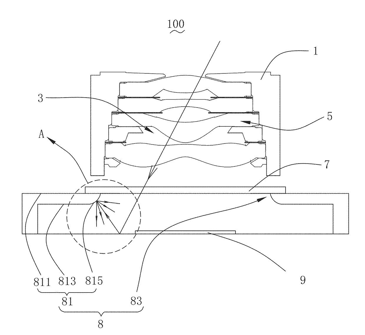
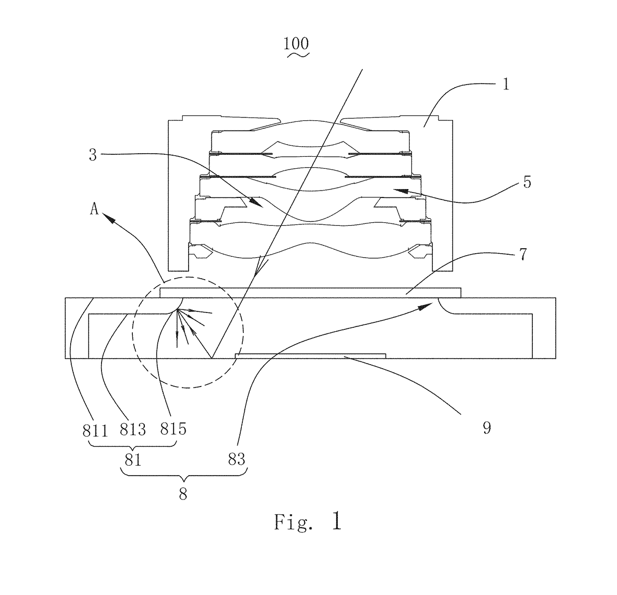
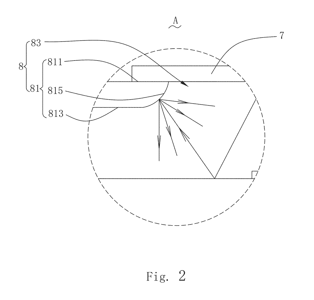
In the relevant technology, a bracket of a lens module has an inclined surface facing towards a sensor, and a light from a filter is reflected by this inclined surface, and a stray light reaches the sensor, and generates a section of purple flash or flare, which seriously impacts an imaging quality of the lens module.

Method used


Image

  • Lens Module
  • Lens Module
  • Lens Module

Examples


Embodiment Construction

[0008]The present disclosure will hereinafter be described in detail with reference to an exemplary embodiment. To make the technical problems to be solved, technical solutions and beneficial effects of the present disclosure more apparent, the present disclosure is described in further detail together with the figure and the embodiment. It should be understood the specific embodiment described hereby is only to explain the disclosure, not intended to limit the disclosure.

[0009]Referring to FIGS. 1-2, a lens module 100 provided by the present disclosure, comprises a lens barrel 1, a lens group 5, a filter 7, a bracket 8 and a sensor 9. The lens barrel 1 has an accommodation space 3, and the lens group 5 is accommodated in the accommodation space 3, and the filter 7, the bracket 8 and the sensor 9 are arranged in turn by an image side of the lens group and outside the accommodation space 3.

[0010]In this embodiment, the filter 7 is an infrared filter, and the bracket 8 is a VCM (voice...


PUM


Abstract

The present disclosure provides a lens module. The lens module includes a lens barrel with an accommodation space; a lens group accommodated in the accommodation space; a filter, a bracket and a sensor set in turn by an image side of the lens group and located outside the accommodation space. The bracket includes a top wall forming an optical aperture. The top wall includes a first surface facing an object side, a second surface opposite to the first surface and a third surface connecting the first surface to the second surface for forming an optical aperture. The third surface is a curved surface.

Description

FIELD OF THE PRESENT DISCLOSURE[0001]The present disclosure relates to a lens module used in a portable or mobile electronic equipment.DESCRIPTION OF RELATED ART[0002]With a rapid development of a multimedia technology, a digital camera, a camera and a cell phone with a webcam are more and more popular among extensive consumers, and a production to the digital camera, camera and cell phone is increasing gradually, and a requirement to the product cost and product quality is also increasing gradually, however, a bracket for a lens module is one of key components that impacts the product quality and production cost.[0003]In the relevant technology, a bracket of a lens module has an inclined surface facing towards a sensor, and a light from a filter is reflected by this inclined surface, and a stray light reaches the sensor, and generates a section of purple flash or flare, which seriously impacts an imaging quality of the lens module.[0004]Therefore it is necessary to provide an impro...

Claims


Application Information

Patent Timeline
IPC IPC(8): G01J1/02G02B7/02G02B5/20G01J1/04G02B7/00G03B11/00
CPCG01J1/0214G02B7/021G02B5/208G01J1/0488G01J1/0411G02B5/021G02B27/0018G01J1/0403
Inventor WAN, JIA
Owner AAC OPTICS SOLUTIONS PTE LTD
Learn More