Lighting device for inspection and inspection system

a technology of inspection object and light source, which is applied in the direction of measuring device, optically investigating flaws/contamination, instruments, etc., can solve the problems of difficult identification of feature points, difficulty in identifying points on inspection object surface, and difficulty in capturing images

Active Publication Date: 2018-10-18
MACHINE VISION LIGHTING INC
View PDF8 Cites 9 Cited by
  • Summary
  • Abstract
  • Description
  • Claims
  • Application Information

AI Technical Summary

Benefits of technology

[0027]As described above, according to the inspection lighting device and the inspection system of the present invention, it is possible to freely adjust the sizes and forms of irradiation solid angles of inspection light irradiated onto respective points on an inspection object and dark areas thereof as well as solid angle regions that are formed within each irradiation solid angle and that have different wavelength bands, polarization planes, or light amounts. Thus, inclusive relations of solid angles of reflected light, transmitted light, or scattered light from respective points on the inspection object and solid angle regions that have different wavelength bands, polarization planes, or light amounts and that are reflected in those solid angles with observation solid angles that are formed at the respective points on the inspection object by the imaging device can be set to be substantially uniform. Therefore, even minute defects and the like that have conventionally been difficult to detect can be detected under substantially the same conditions.

Problems solved by technology

More particularly, there are cases where, since a product to be inspected does not have the surface characteristics of a perfect mirror surface, precision control of the optical axis and the shape and the like of an irradiation solid angle for obtaining desired gradation information regarding a feature point on the inspection object surface is difficult, and even if the inspection light can be irradiated, significant contrast variation may occur depending on the position on the inspection object at which the feature point is present, making it difficult to identify the feature point.
However, even when reduction of such stray light coming into the imaging device is made possible with the above-described method, in the case of a very small defect or the like, significant variation occurs in the brightness of the captured image, which makes detection thereof as a defect impossible.
Consequently, the machine vision is unable to accurately detect such small defects or the like in the inspection target area.

Method used


Image

  • Lighting device for inspection and inspection system
  • Lighting device for inspection and inspection system
  • Lighting device for inspection and inspection system

Examples


Embodiment Construction

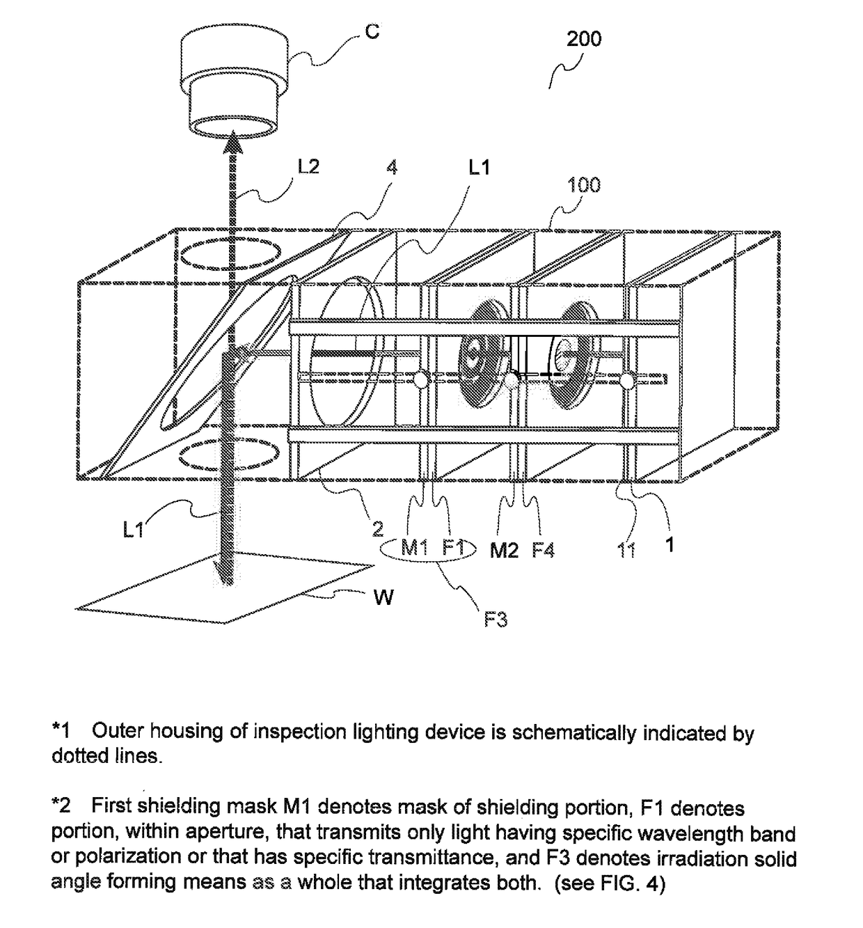
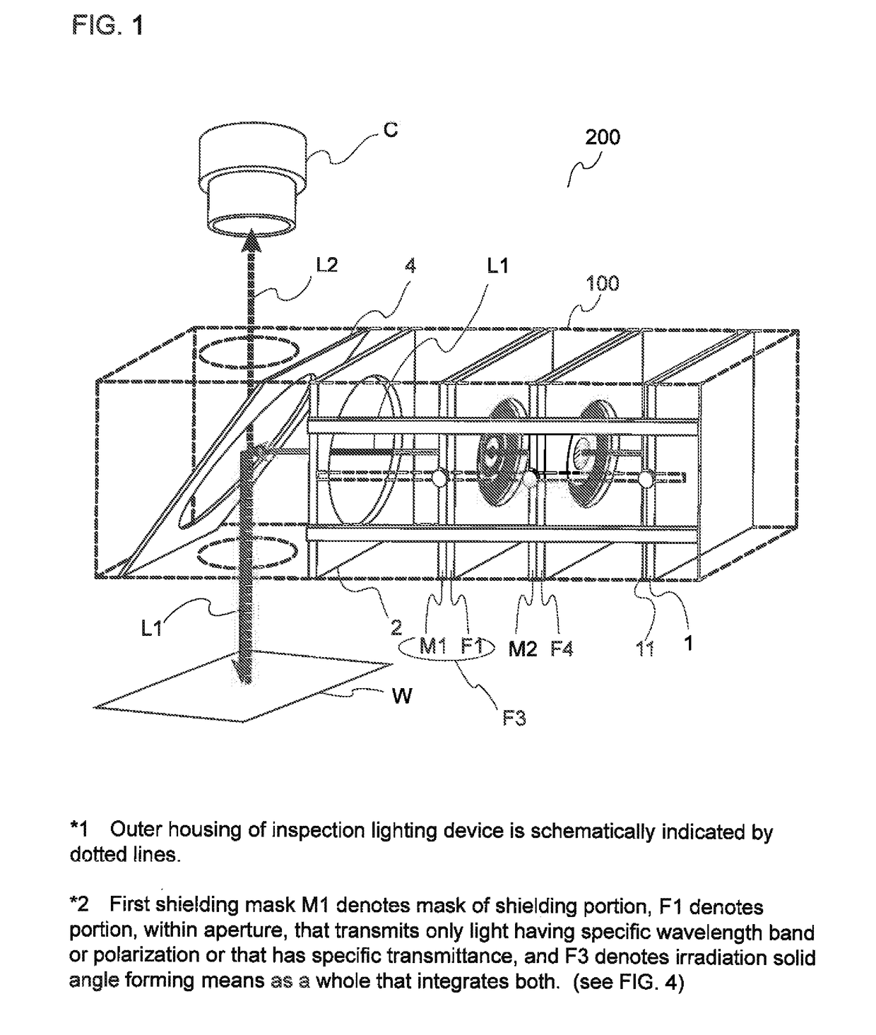
[0041]A first embodiment of the present invention will be described.

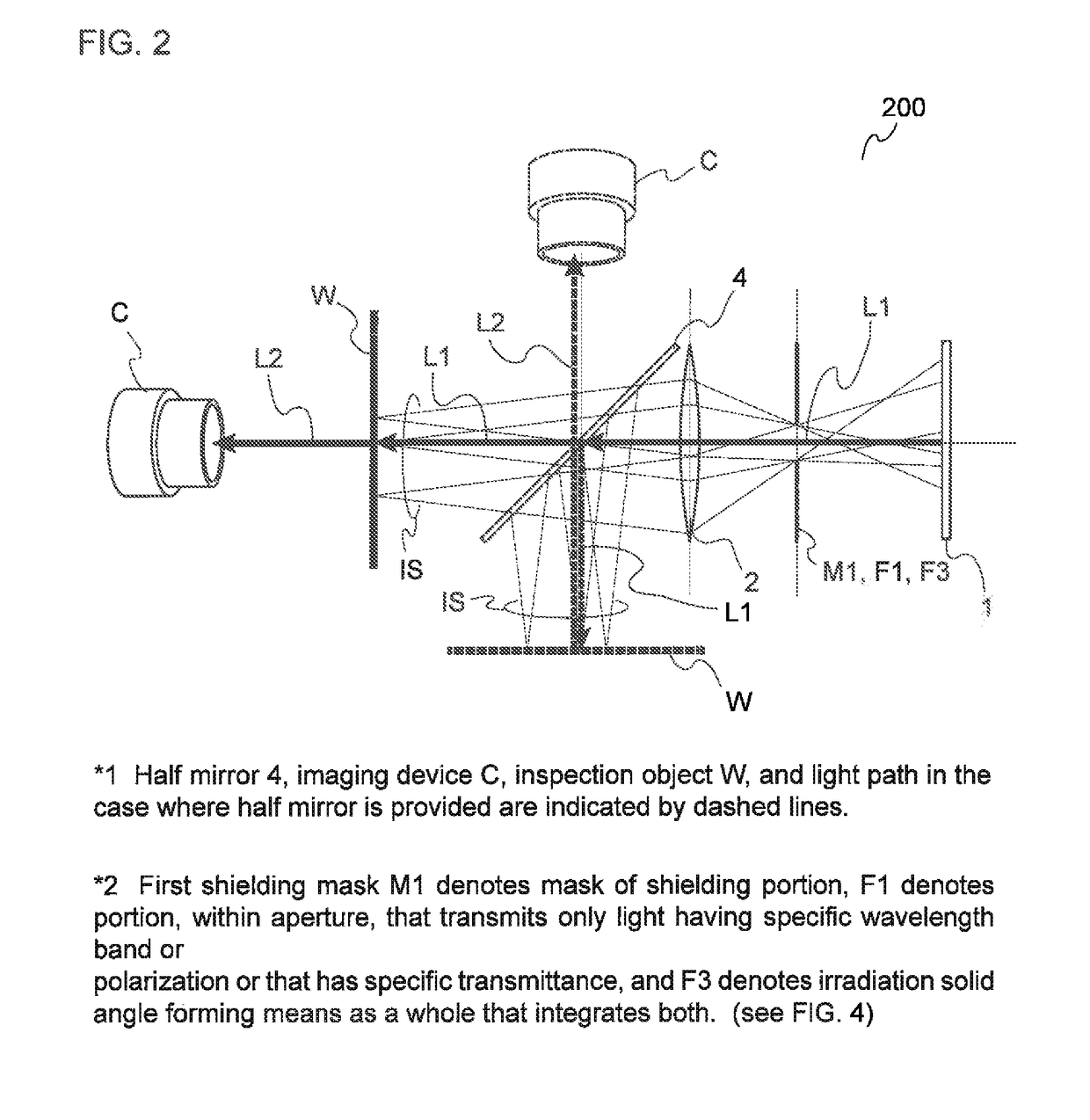
[0042]An inspection system 200 constituted by an inspection lighting device 100 of the first embodiment and an imaging device C is configured to provide a so-called coaxial lighting arrangement using a half mirror 4 for providing agreement between an imaging direction of an inspection object W and a lighting direction of the inspection object W, and is used to cause a feature point such as a defect that is present on the inspection object W to appear as a contrast in an image captured by the imaging device C. It should be noted that, in FIGS. 2 and 5 through 8, a case with a half mirror is indicated by dotted lines, whereas a case without a half mirror is indicated by solid lines. Moreover, a first filter F1 serves as a means for selectively transmitting light having a specific attribute and forming a solid angle region composed of the light having that attribute. In terms of the effect of forming a solid angle, the...


PUM

PropertyMeasurementUnit
solid angleaaaaaaaaaa
irradiation solid angleaaaaaaaaaa
sizeaaaaaaaaaa

Abstract

Provided is an inspection lighting device with which, even when changes in light that occur at respective feature points on an object to be inspected are small, the amounts of those changes in light can be determined across the entire field-of-view range, and the feature points can be detected under exactly the same conditions. An inspection lighting device 100 includes a surface light source 1 and a lens 2 that is disposed between the surface light source 1 and an inspection object W, the lens 2 being disposed nearer to the inspection object W such that at least one of a shielding mask M1 and a filtering means F1 is located centered around a focal distance position of the lens. An irradiation solid angle of light emitted from the surface light source 1 and irradiated onto the inspection object W by the lens 2 is configured to have solid angle regions as desired, the solid angle regions having specific optical attributes. The shapes, sizes, and inclination angles of irradiation solid angles of the inspection light as well as solid angle regions having specific optical attributes within the irradiation solid angles can be set to be substantially uniform across the entire field of view in accordance with changes that occur at feature points on the inspection object.

Description

TECHNICAL FIELD[0001]The present invention relates to a lighting device for inspection for use in inspecting an appearance, damage, a defect or the like of a product by, for example, irradiating inspection light onto a product which is an inspection object. The invention relates also to an inspection system.BACKGROUND ART[0002]As an example of an inspection lighting device for use in, for example, inspection of an appearance of a product, it is possible to cite a coaxial lighting device shown in Patent Document 1, in which an imaging direction is in agreement with a lighting direction for an inspection object. This coaxial lighting device includes a light source configured to emit inspection light in a direction parallel to an inspection object surface of the inspection object, and a half mirror disposed with an inclination between the inspection object and an imaging (image pick-up) device disposed upward of the inspection object and configured to reflect the inspection light towar...

Claims


Application Information

Patent Timeline
Patent Type & Authority Applications(United States)
IPC IPC(8): G01N21/88G01N21/956
CPCG01N21/8806G01N21/95623G01N2201/0636
Inventor MASUMURA, SHIGEKI
Owner MACHINE VISION LIGHTING INC
Why Eureka
Try Eureka