Method of detecting fraud
a fraud detection and fraud technology, applied in the field of fraud detection, can solve the problems of degrading the ergonomy of the sensor, the method is not robust to mindful fraud, etc., and achieve the effect of improving the detection of fraud
- Summary
- Abstract
- Description
- Claims
- Application Information
AI Technical Summary
Benefits of technology
Problems solved by technology
Method used
Image
Examples
first embodiment
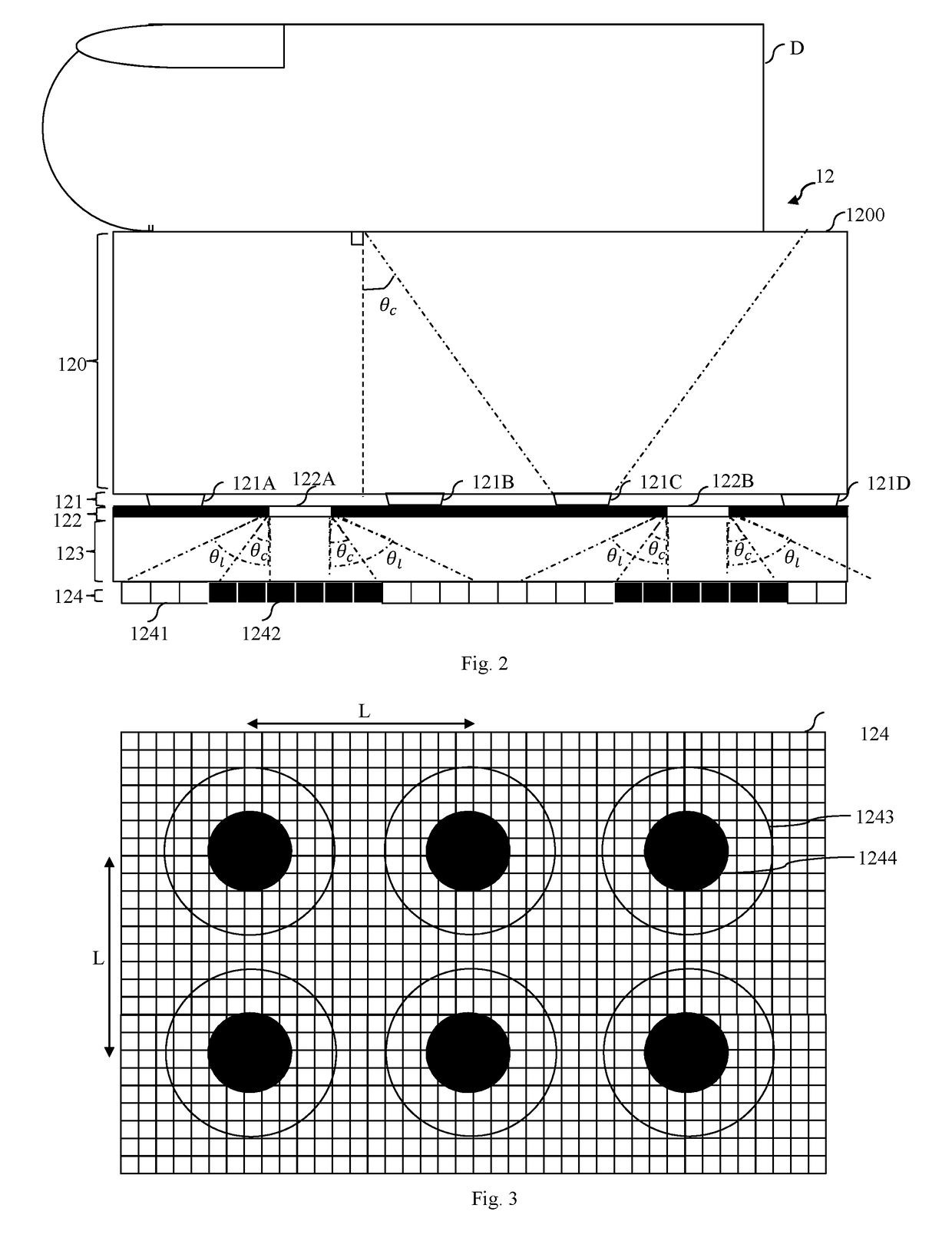
[0045]FIG. 2 schematically illustrates the biometric device 12 adapted to implement the method according to the invention.
[0046]The biometric device 12 uses the principle of total internal reflection with dark field that we recall hereinbelow in conjunction with FIG. 5.
[0047]FIG. 5 schematically describes a device for capturing a fingerprint working in total internal reflection and operating in a dark field.
[0048]The device 50 described in FIG. 5 comprises a prism 500, a light source 501B, and an optical system 502 such as for example a CCD (“Charge-Coupled Device”) or CMOS (“Complementary Metal Oxide Semiconductor”) sensor and one or more lenses.
[0049]The light source 501B generates a light beam which passes through a first face 500B of the prism 500 to a second face 500C of the prism 500 where a finger D is positioned. The light beam generated by the light source 501B forms an incident angle αB with the normal to the face 500C smaller than a critical angle θc and than a limit angl...
second embodiment
[0087]FIG. 4A schematically illustrates the biometric device 12 according to the invention.
[0088]In this embodiment, we again find the plate 120, the opaque screen 122, the plate 123 and the sensor 124.
[0089]In this embodiment, the light source is no longer situated at the level of the opaque screen 122. LEDs are inserted at the level of the sensor 124, i.e. under the opaque screen 122. At least some of the holes of the opaque screen 122 have an LED facing them.
[0090]In order that the whole of the finger D opposite the upper face 1200 scatters light, the holes of the opaque screen 122 having a LED facing them are arranged in such a way that each LED and the LED or LEDs which are the nearest neighbours of the said LED generate parts directly illuminated by the LEDs which are a distance δ apart that is smaller than the distance dp.
[0091]Moreover, in order to avoid overlaps between the incidence zones, in all the particular implementations relating to the embodiment of FIG. 4A, the hol...
PUM
 Abstract
Description
Claims
Application Information
 - R&D
- Intellectual Property
- Life Sciences
- Materials
- Tech Scout
- Unparalleled Data Quality
- Higher Quality Content
- 60% Fewer Hallucinations
Browse by: Latest US Patents, China's latest patents, Technical Efficacy Thesaurus, Application Domain, Technology Topic, Popular Technical Reports.
© 2025 PatSnap. All rights reserved.Legal|Privacy policy|Modern Slavery Act Transparency Statement|Sitemap|About US| Contact US: help@patsnap.com


