Improvements in or relating to direct current protection schemes

a protection scheme and direct current technology, applied in the direction of fault location by conductor type, fault location by pulse reflection method, instruments, etc., can solve the problem that the protection device cannot be operated quickly enough, and achieve the effect of improving the accuracy of comparison

Active Publication Date: 2018-10-18
GENERAL ELECTRIC TECH GMBH
View PDF4 Cites 16 Cited by
  • Summary
  • Abstract
  • Description
  • Claims
  • Application Information

AI Technical Summary

Benefits of technology

[0015]The foregoing configuration of the controller provides a reliable means for using local measurements to identify the direction of the electrical fault.
[0016]In further embodiments of the invention, the controller may be programmed to modify each travelling wave to remove a pre-fault component. The controller may be programmed to obtain the travelling wave norm values from the modified forward and backward travelling waves. This improves the accuracy of the comparison between the obtained travelling wave norm values to identify the direction of the electrical fault.

Problems solved by technology

The aforementioned functionality is especially desirable when the considerable length of a DC power transmission medium, e.g. several hundred kilometres, means that communication with one or more remote elements is unreliable, or the resulting delay in receiving information once communication is established is such that an associated protection device cannot be operated quickly enough to provide meaningful protection.

Method used


Image

  • Improvements in or relating to direct current protection schemes
  • Improvements in or relating to direct current protection schemes
  • Improvements in or relating to direct current protection schemes

Examples


Embodiment Construction

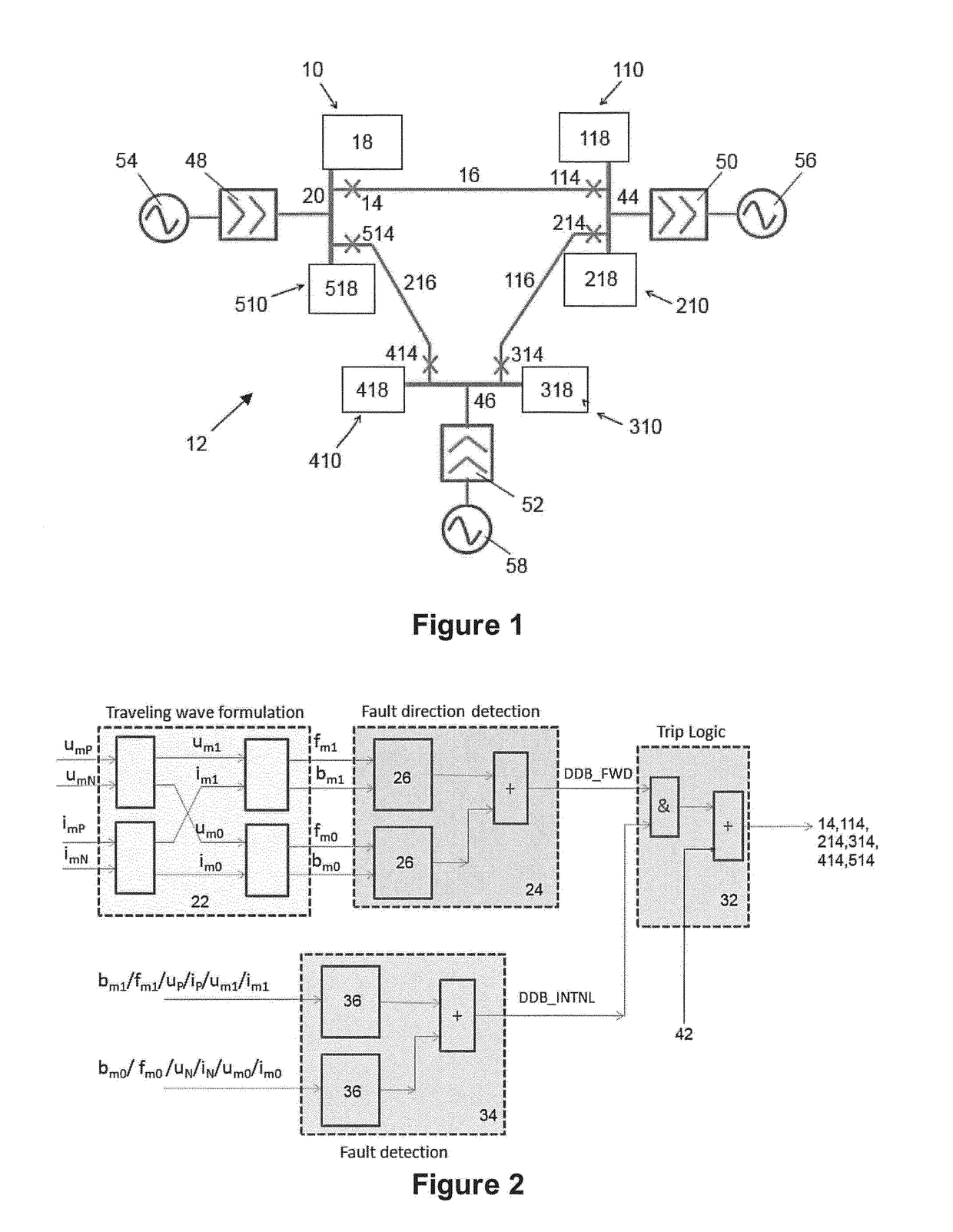
[0036]A DC protection scheme according to a first embodiment of the invention is designated generally by reference numeral 10 and forms part of a DC electrical power network 12 in the form of a DC grid, as shown schematically in FIG. 1.

[0037]The first DC protection scheme 10 includes a first protection device 14 which, in the embodiment shown is a circuit breaker, although other types of protection devices such as a relay are also possible. The first protection device 14, i.e. circuit breaker, is electrically coupled in use to a DC power transmission medium 16, i.e. arranged in-line with the DC power transmission medium 16, and is operable to protect the DC power transmission medium 16 from an electrical fault, i.e. tripping the circuit breaker to clear the electrical fault inside the DC power transmission medium 16.

[0038]The DC protection scheme 10 also includes a first measurement apparatus (not shown) which is able to selectively measure the voltages and currents of the DC power ...


PUM


Abstract

A DC protection scheme for protecting a DC power transmission medium within a DC electrical power network. The scheme includes a protection device coupled to a DC power transmission medium, being operable to protect the power transmission medium from a fault; an apparatus to measure at least one electrical property of the power transmission medium; and a controller programmed to determine the direction of the electrical fault; determine whether the electrical fault is an internal or external fault; and operate the protection device to protect the DC power transmission medium if the determination of the direction of the electrical fault and/or the determination of whether the electrical fault is an internal or external fault meet a predefined criterion.

Description

FIELD OF INVENTION[0001]Embodiments of the invention relate to a direct current (DC) protection scheme and a DC electrical power network including a plurality of such schemes.BACKGROUND OF THE INVENTION[0002]DC electrical power networks, such as DC grids, typically include a plurality of terminals each of which may be operatively associated with a power converter to interconnect the DC power transmission network with a respective alternating current (AC) network.[0003]Respective pairs of terminals are interconnected by a section of DC power transmission medium, such as a transmission line or cable. Protection devices, such as circuit breakers and relays, are operated in the event of a fault to protect the DC electrical power network.SUMMARY OF INVENTION[0004]According to a first aspect of embodiments of the invention, there is provided a DC protection scheme for protecting a DC power transmission medium within a DC electrical power network, the DC protection scheme comprising: a pro...

Claims


Application Information

Patent Timeline
Patent Type & Authority Applications(United States)
IPC IPC(8): H02H7/26H02H1/00G01R31/08
CPCH02H7/265H02H1/0007H02H7/268G01R31/085Y02E60/60G01R23/167G01R31/11H02H7/263H02H3/28G01R31/08H02H3/44
Inventor HA, HENGXUSRI GOPALA KRISHNA MURTHI, SANKARA SUBRAMANIAN
Owner GENERAL ELECTRIC TECH GMBH
Why Eureka
Try Eureka