Steerable TLIF Spine Implants

Active Publication Date: 2018-10-25
LIFE SPINE INC
View PDF2 Cites 61 Cited by
  • Summary
  • Abstract
  • Description
  • Claims
  • Application Information

AI Technical Summary

Problems solved by technology

While some of these issues can be alleviated...

Method used


Image

  • Steerable TLIF Spine Implants
  • Steerable TLIF Spine Implants
  • Steerable TLIF Spine Implants

Examples


Embodiment Construction

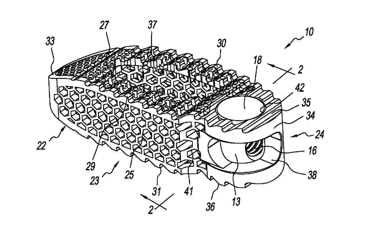
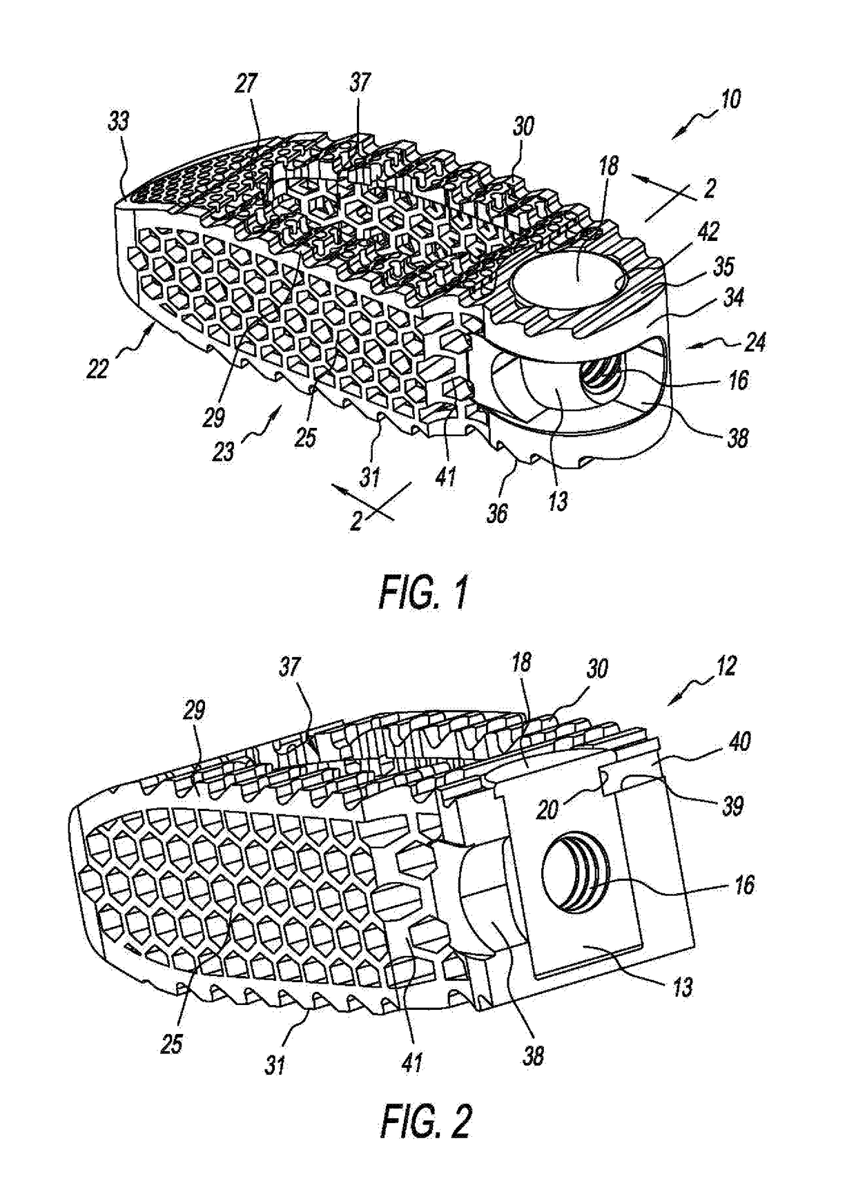
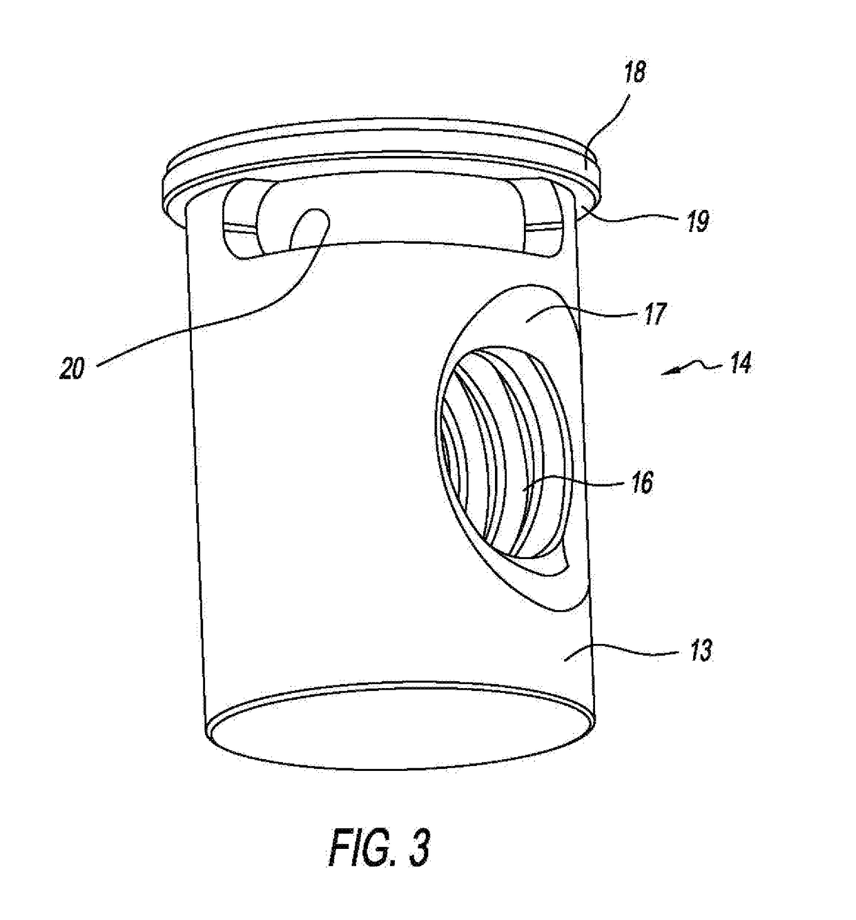
[0027]Referring to FIGS. 1-3, there is depicted an exemplary form of a transforaminal lumbar interbody fusion (TLIF) implant (spine implant), generally designated 10, fashioned in accordance with the present principles, that is able to be steered or guided into a vertebral space via an installation instrument. The TLIF implant 10 is made from a biocompatible material such as, but not limited to, titanium, stainless steel, an alloy of titanium or stainless steel, PEEK, solid PEEK, other plastics and polymers, and otherwise. The TLIF implant 10 is characterized by a cage or interbody device 12 and a post 14. The post 14 is preferably, but not necessarily, removable from and insertable into the cage 12 and allows the cage 12 to rotate relative to the post 14.

[0028]The post 14 is particularly shown in FIG. 3. The post 14 has a generally cylindrical body 13 with a head 18 on one end defining an under surface 19. As seen in FIG. 2, the under surface 19 is retained by a ledge of a bore of ...


PUM


Abstract

A spine implant for a TLIF surgical procedure is configured to be steered into place during implantation in conjunction with a complementary insertion instrument. The cage of the implant is constrained to a limited range of rotation about a post carried by the cage. The insertion instrument is configured to hold the post while controllably rotating the cage relative to the post in order to angularly position the implant during implantation. Range of rotational motion is controlled by the configuration of a groove in the post. A retaining pin of the implant extends from the cage into the groove of the post to rotationally connect the cage to the post.

Description

CROSS-REFERENCE TO RELATED APPLICATIONS[0001]This U.S. non-provisional patent application claims the benefit of and / or priority under 35 U.S.C. § 119(e) to U.S. provisional patent application Ser. No. 62 / 487,114 filed Apr. 19, 2017 titled “Steerable TLIF Spine Implants,” the entire contents of which is specifically incorporated herein by reference.FIELD OF THE INVENTION[0002]The present invention relates to methods and devices for orthopedic surgery of the spine and particularly, to devices and methods for transforaminal lumbar interbody fusion (TLIF).BACKGROUND OF THE INVENTION[0003]Many people contend with spine issues as a result of age, disease, and trauma, as well as congenital and acquired complications and conditions. While some of these issues can be alleviated without surgery, other issues necessitate surgery. Spinal fusion may be recommended for conditions such as spondylolistheses, degenerative disc disease, or recurrent disc herniation, and is designed to create solid bo...

Claims


Application Information

Patent Timeline
IPC IPC(8): A61F2/44A61F2/46A61F2/30
CPCA61F2/447A61F2/4611A61F2/446A61F2/30771A61F2002/30224A61F2002/30405A61F2002/30538A61F2002/4629A61F2310/00023A61F2310/00017A61F2002/30153A61F2002/30784A61F2002/30904A61F2002/4623A61F2002/4625A61F2/4465A61F2002/30133A61F2002/3054A61F2002/3082A61F2002/3092A61F2002/3093A61F2002/4622A61F2002/4628A61F2/4603A61F2002/30593
Inventor SHOSHTAEV, EUGENE
Owner LIFE SPINE INC
Why Eureka
Try Eureka