Process for manufacturing filler tube and filler tube

Inactive Publication Date: 2018-10-25
TOKAI RUBBER IND LTD
View PDF0 Cites 0 Cited by
  • Summary
  • Abstract
  • Description
  • Claims
  • Application Information

AI Technical Summary

Benefits of technology

[0015]The flange further includes a first end face to be welded onto an outer face of the fuel tank, an outer peripheral face, and a second end face making a rear-face side of the first end face. All of the first end face, outer peripheral face and second end face are formed by an outermost layer making the flange. The flange has a diametrical thickness being greater than another diametri

Problems solved by technology

Consequently, the interspaces, which exist between the crests in a bellows, make it impo

Method used


Image

  • Process for manufacturing filler tube and filler tube
  • Process for manufacturing filler tube and filler tube
  • Process for manufacturing filler tube and filler tube

Examples


first embodiment

4. Detailed Construction of Weld End Portion 31

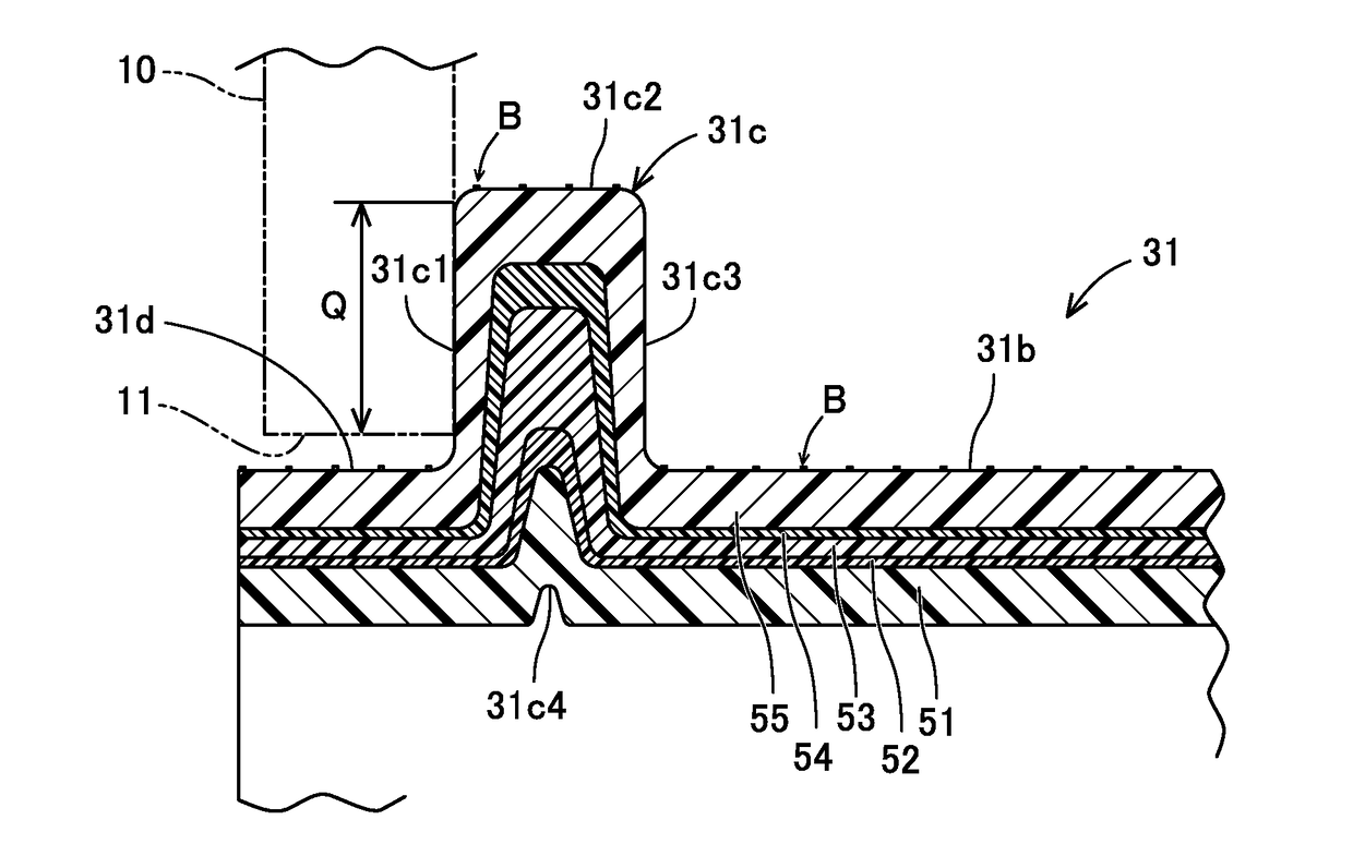
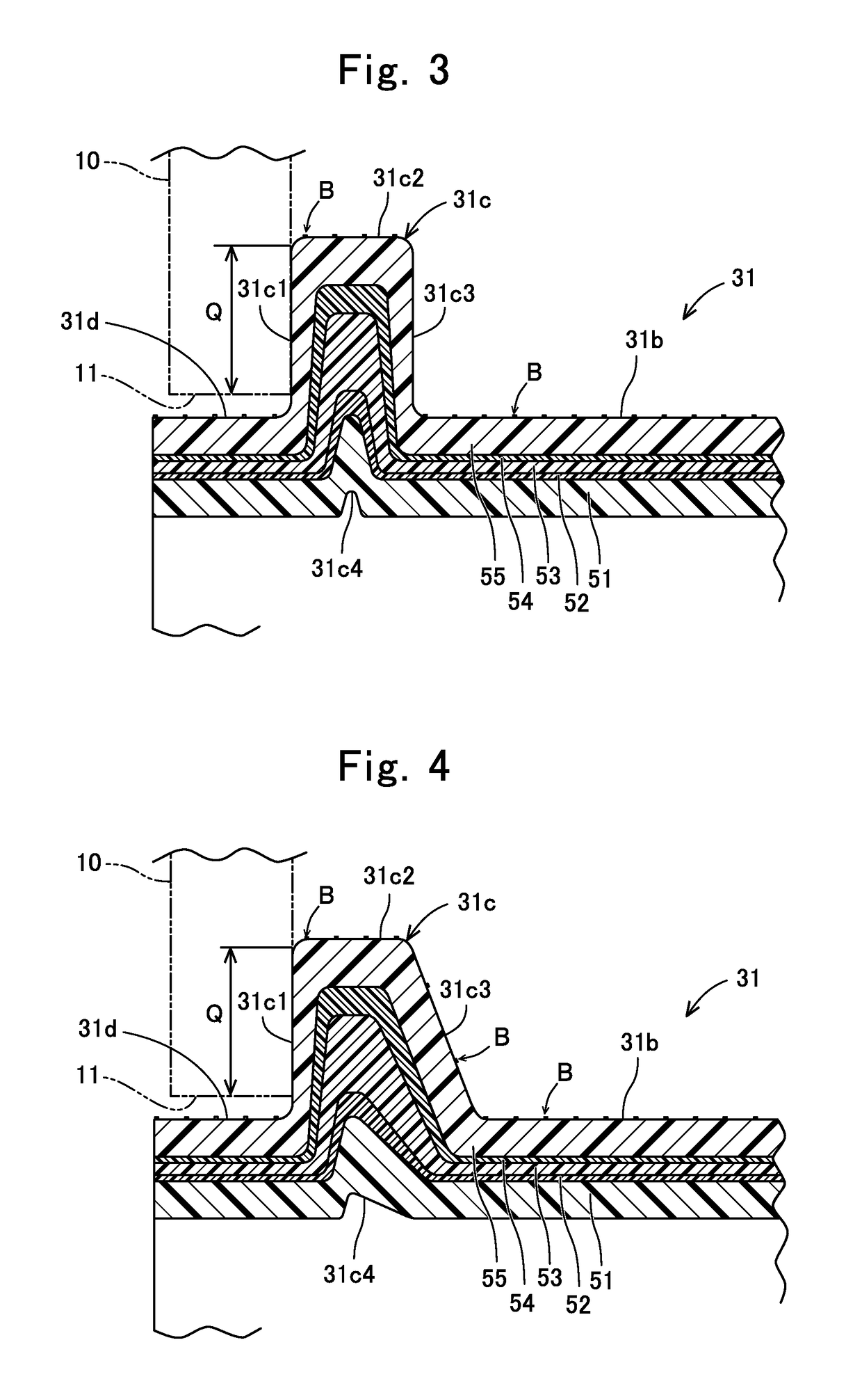
[0037]A detailed construction of the weld end portion 31 according to First Embodiment will be hereinafter described with reference to FIG. 3. The flange 31c of the weld end portion 31 comprises a first end face 31c1, an outer peripheral face 31c2, and a second end face 31c3. The first end face 31c1 is located on an imaginary plane intersecting perpendicularly with the axial direction of the weld end portion 31. The first end face 31c1 is to be welded onto the fuel tank 10 over a diametrical range “Q.” The outer peripheral face 31c2 is formed in the shape of a circularly cylindrical face.

[0038]The second end face 31c3 is located on a rear-face side of the first end face 31c1. The second end face 31c3 is formed parallel to the first end face 31c1. That is, the second end face 31c3 is located on another imaginary plane intersecting perpendicularly with the axial direction of the weld end portion 31. The second end face 31c makes a face wh...

second embodiment

5. Detailed Construction of Weld End Portion 31

[0046]A detailed construction of the weld end portion 31 according to Second Embodiment will be hereinafter described with reference to FIG. 4. Only a part, which is distinct from those of the weld end portion 31 according to First Embodiment, will be described hereinbelow. The flange 31c of the weld end portion 31 comprises a first end face 31c1, an outer peripheral face 31c2, and a second end face 31c3. The second end face 31c3 includes an inclined face inclined relative to the axial direction of the weld end portion 31. In more detail, a normal line to the second end face 31c3 has an axial component headed for an opposite side to the fuel tank 10, and a diametrical component headed outward. That is, the flange 31c has an axial width which becomes smaller as it approaches the outer peripheral side, and which becomes larger as it approaches the inner peripheral side. The inclined second end face 31c3 is securely suctioned or drawn in t...


PUM

PropertyMeasurementUnit
Thicknessaaaaaaaaaa
Diameteraaaaaaaaaa

Abstract

A filler tube including a cylindrical body and flange is manufactured using a cylindrical workpiece. A material forms an outermost layer in the cylindrical body and flange of the cylindrical workpiece. Dividable molds move at a first speed upon adhering the cylindrical workpiece onto the site for forming the cylindrical body, thereby giving the cylindrical body a predetermined diametrical thickness; and then move at a second speed being slower than the first speed upon adhering the cylindrical workpiece onto the other site for forming the flange, thereby filling up the flange with the material and other materials for forming the flange over a diametrical range to be welded onto the fuel tank while making the diametrical thickness of the flange greater than that of the cylindrical body.

Description

CROSS REFERENCE TO RELATED APPLICATIONS[0001]The present application is a Continuation Application of International Application No. PCT / JP2018 / 000141, filed on Jan. 9, 2018, which is incorporated herein by reference. The present invention is based on Japanese Patent Application No. 2017-013636, filed on Jan. 27, 2017, the entire contents of which are incorporated herein by reference.BACKGROUND OF THE INVENTION1. Field of the Invention[0002]The present invention relates to a process for manufacturing filler pipe, and a filler pipe.2. Description of the Related Art[0003]Japanese Unexamined Patent Publication (KOKAI) Gazette No. 2003-194280, and Japanese Unexamined Patent Publication (KOKAI) Gazette No. 2008-162436 disclose a filler tube to be welded onto a fuel tank, respectively. FIG. 6 of Japanese Unexamined Patent Publication (KOKAI) Gazette No. 2003-194280 illustrates that the filler tube comprises a flange in which a material making the outermost layer is welded onto the fuel tan...

Claims


Application Information

Patent Timeline
IPC IPC(8): B60K15/04B29C47/00B29C47/06B29C48/09B29C48/13B29C48/335B29C48/90B29C48/92
CPCB60K15/04B29C47/0023B29C47/0061B29C47/067B60K2015/0464B60K2015/0477B29L2023/183B29K2023/065B29K2023/086B29K2077/00B29K2995/0067B29K2995/0069F16L9/12B29C48/92B29C48/18B29C48/335B29C48/90B29C66/0222B29C66/131B29C66/522B29C66/534B29C66/54B29L2031/7172B29C66/7392B29C66/53246B60K2015/047B29C57/04B29C57/08B29C48/002B29C48/09B29C48/22B29C48/13
Inventor WAKAZONO, YUKINORIFUKUYASU, TOMOYUKIMIZUNO, FUMIYASHIMOJO, MAKOTOJIANG, LINMIYAJIMA, ATSUO
Owner TOKAI RUBBER IND LTD
Why Eureka
Try Eureka