Supercharge Your Innovation With Domain-Expert AI Agents!

Inverted pendulum type vehicle

a technology of pendulum and vehicle, which is applied in the direction of cycle equipment, transportation and packaging, cycle, etc., can solve the problems of preventing vehicle travel, affecting the normal travel of the vehicle, and the estimated value of the actual travel velocity of the overall center of gravity of the traveling motion unit. achieve the effect of maximizing the continuance of normal travel motion of the vehicl

Active Publication Date: 2018-10-25
HONDA MOTOR CO LTD
View PDF0 Cites 2 Cited by
  • Summary
  • Abstract
  • Description
  • Claims
  • Application Information

AI Technical Summary

Benefits of technology

The present invention provides an inverted pendulum type vehicle that can maximize its normal travel motion by controlling a traveling motion unit when idling occurs. The invention includes a desired motion correction unit that reduces the frequency component of velocity difference by correcting the reference desired motion based on the high-frequency idling state amount. This ensures that the vehicle can quickly clear or reduce idling when it occurs, and can move in a motion state that coincides or substantially coincides with the reference desired motion when no idling or subtle idling occurs. The idling of the traveling motion unit tends to occur when the driving force applied to it is increasing, so the invention also includes a driving force increasing state to prevent excessive idling. Overall, the invention enables the vehicle to continue performing normal travel motion to the maximum extent possible.

Problems solved by technology

When the inverted pendulum type vehicle travels, in a situation in which, for example, the traveling motion unit is moved to ride over a step or a projection on a floor surface, there are cases where the traveling motion unit runs idle due to a slippage between the traveling motion unit and the floor surface.
However, various experiments or studies performed by the inventors of the present application have disclosed that the conventional techniques described in Patent Documents 1 and 2 present the following inconveniences.
In this case, the estimated value of the actual travel velocity of the overall center of gravity of the traveling motion unit or the vehicle is apt to include a steady (or a low-frequency range) error mainly because of the influence of the output drift of the acceleration sensor or the integration error of acceleration detection values.
This inconveniently leads to frequent occurrence of a situation in which the travel of the vehicle is prevented due to such detection of idling.

Method used


Image

  • Inverted pendulum type vehicle
  • Inverted pendulum type vehicle
  • Inverted pendulum type vehicle

Examples


first embodiment

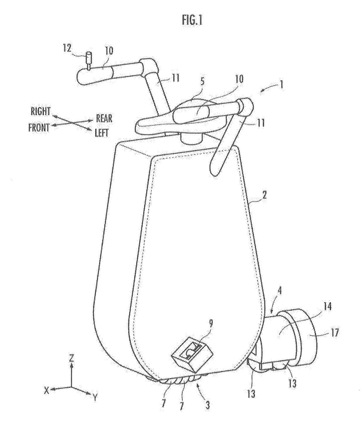
[0051]A first embodiment of the present invention will be described with reference to FIG. 1 to FIG. 13. Referring to FIG. 1 and FIG. 2, an inverted pendulum type vehicle 1 (hereinafter may be referred to simply as “the vehicle 1”) according to the present embodiment includes a base frame 2, a first traveling motion unit 3 and a second traveling motion unit 4, which are capable of traveling on a floor surface, and a saddle unit 5 on which a rider mounts.

[0052]The first traveling motion unit 3 includes a ring-shaped core member 6 (hereinafter referred to as “the annular core 6”) illustrated in FIG. 2 and a plurality of annular rollers 7, which are attached to the annular core 6 and which are arranged at equiangular intervals in the circumferential direction (the direction about the axis) of the annular core 6. The rollers 7 are externally inserted in the annular core 6 with the rotational axes thereof directed in the circumferential direction of the annular core 6. Further, the rolle...

second embodiment

[0227]A description will now be given of a second embodiment of the present invention with reference to FIG. 14. The present embodiment differs from the first embodiment only in the processing by a velocity-at-idling regulator 212. Therefore, the description of the present embodiment will be focused mainly on the aspects that are different from the first embodiment, and the description of the same aspects as those of the first embodiment will be omitted.

[0228]Referring to FIG. 14, regarding the processing carried out by the velocity-at-idling regulator 212 in the present embodiment, the processing from a processing section 42a to a processing section 42f is the same as that of the first embodiment. According to the present embodiment, the velocity-at-idling regulator 212 determines, as a translational velocity correction amount ΔVc_xy, a value that is obtained by multiplying, by a processing section 42h, each component of an output of the processing section 42f by a value of a power...

third embodiment

[0237]Referring now to FIG. 15, a third embodiment of the present invention will be described. The present embodiment differs from the first embodiment only in the processing carried out by a speed-at-idling regulator 212. Therefore, the description of the present embodiment will be focused mainly on the aspects that are different from the first embodiment, and the description of the same aspects as those of the first embodiment will be omitted.

[0238]Referring to FIG. 15, the speed-at-idling regulator 212 in the present embodiment includes a high-frequency idling amount estimator 216 which determines an idling amount ΔV1(h)_xy in a high-frequency range of a first traveling motion unit 3 by the processing obtained by partly modifying the processing carried out by the foregoing idling amount estimator 214.

[0239]The high-frequency idling amount estimator 216 carries out, by a ground contact point acceleration calculator 44a, the same processing as the processing carried out by the grou...


PUM


Abstract

Provided is an inverted pendulum type vehicle. A controller (20) includes a reference desired motion determiner (211), which sequentially determines a reference desired motion of a traveling motion unit (3) so as to stabilize the attitude of an object mounting unit (5), high-frequency idling state amount calculators (214), (42a) and (42b), which calculate the high-frequency idling state amount of the traveling motion unit (3), and a desired motion corrector (42g), which corrects the reference desired motion by a correction amount determined on the basis of the high-frequency idling state amount to reduce a high-frequency component of idling. The controller (20) controls an actuator unit (8) according to the desired motion obtained by correcting the reference desired motion.

Description

BACKGROUND OF THE INVENTIONField of the Invention[0001]The present invention relates to an inverted pendulum type vehicle.Description of the Related Art[0002]Hitherto, there has been known an inverted pendulum type vehicle described in, for example, Japanese Patent Application Laid-Open No. 2013-237324 (hereinafter referred to as “Patent Document 1”) and Japanese Patent Application Laid-Open No. 2011-105072 (hereinafter referred to as “Patent Document 2”). This type of inverted pendulum type vehicle has a traveling motion unit capable of traveling on a floor surface, an actuator unit that drives the traveling motion unit, a base to which the traveling motion unit and the actuator unit are assembled, an object mounting unit (a part on which a rider mounts or an object to carry is mounted) which is assembled to the base and tiltable with respect to the vertical direction, and a controller that controls the operation of the actuator unit.[0003]In the inverted pendulum type vehicle, the...

Claims


Application Information

Patent Timeline
IPC IPC(8): B62K11/00B62K1/00
CPCB62K11/007B62K1/00B62K17/00B62J45/414B62J45/42B62K11/14B62K23/06
Inventor MURAKAMI, HIDEOOZAKI, KAZUMASAKAWAKAMI, TOMOHIROAKIMOTO, KAZUSHI
Owner HONDA MOTOR CO LTD
Features
  • R&D
  • Intellectual Property
  • Life Sciences
  • Materials
  • Tech Scout
  • Unparalleled Data Quality
  • Higher Quality Content
  • 60% Fewer Hallucinations
Learn More