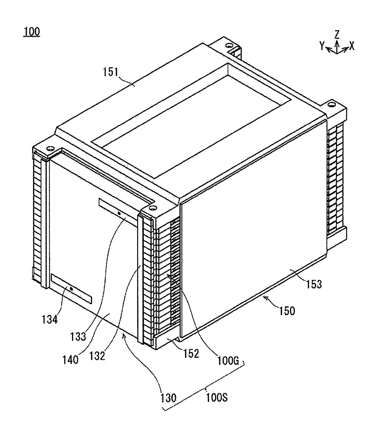
Battery pack and battery pack manufacturing method
a battery pack and manufacturing method technology, applied in the field of batteries, can solve the problems of insufficient bonding of electrode tabs, insufficient insertion of electrode tabs into the recessed portions of the bus bar, and inability to secure electrical conductivity
- Summary
- Abstract
- Description
- Claims
- Application Information
AI Technical Summary
Benefits of technology
Problems solved by technology
Method used
Image
Examples
first embodiment
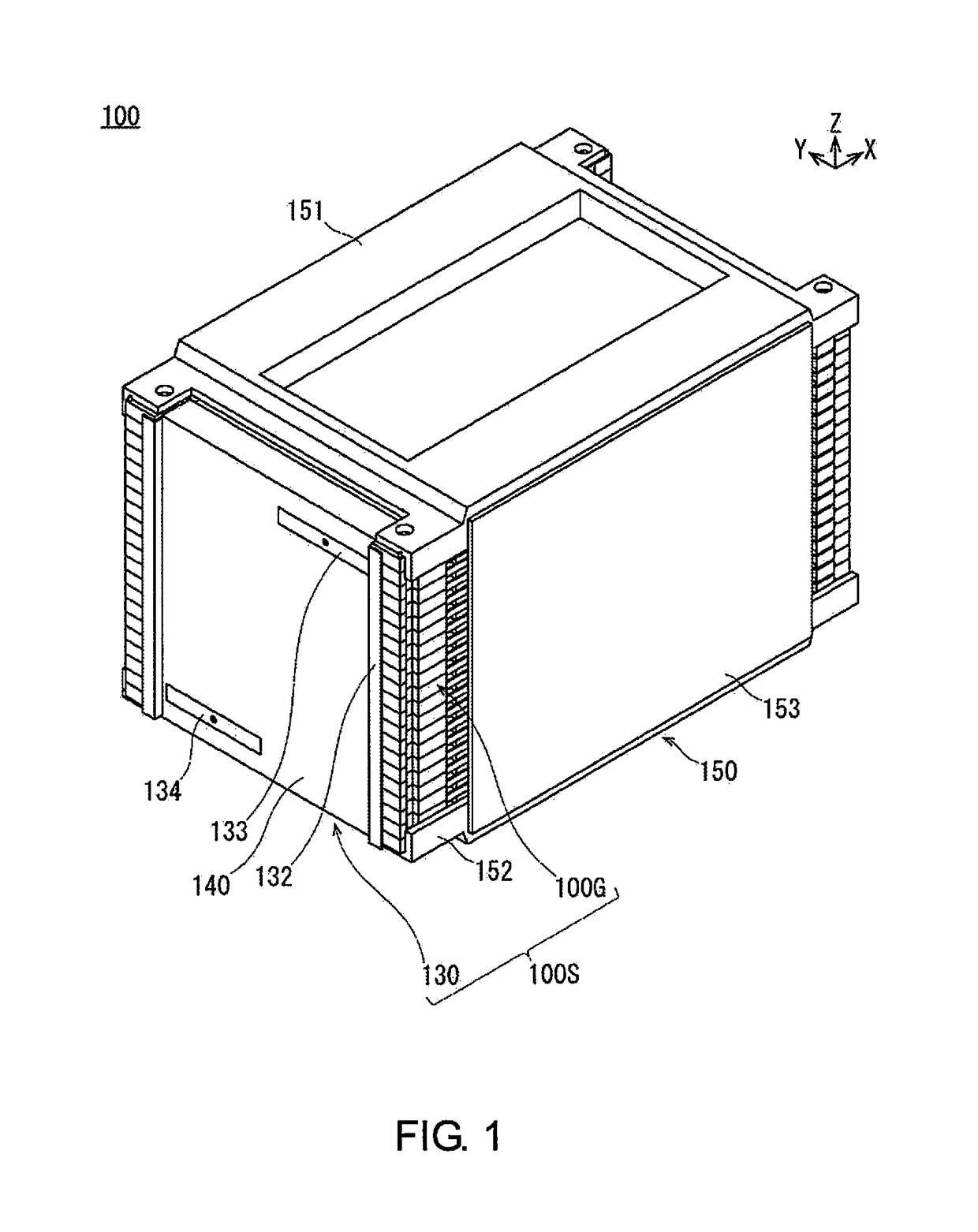
[0039]First, a battery pack 100 according to the first embodiment will be described with reference to FIGS. 1-9.
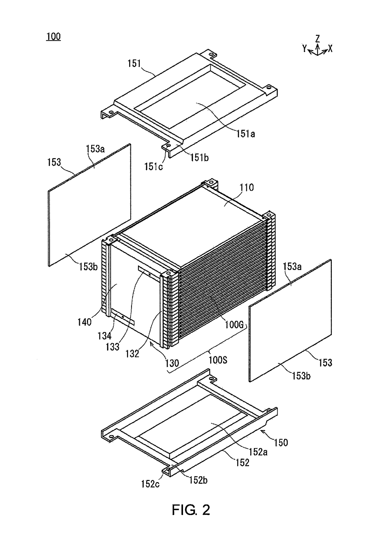
[0040]FIG. 1 is a perspective view illustrating the battery pack 100 according to the first embodiment. FIG. 2 is a perspective view illustrating a state in which an entire stack body 100S, in a state in which an upper pressure plate 151, a lower pressure plate 152, and left and right side plates 153 are disassembled from the battery pack 100 illustrated in FIG. 1 and a protective cover 140 is attached thereto, is exposed. FIG. 3 is a perspective view illustrating a state in which the protective cover 140 is detached from the stack body 1005 illustrated in FIG. 2, and the stack body 100S is disassembled into a cell group 100G and a bus bar unit 130. FIG. 4 is an exploded perspective view illustrating the bus bar unit 130 illustrated in FIG. 3. FIG. 5 is an exploded perspective view schematically illustrating a state in which an anode side electrode tab 113A of a first cell...
second embodiment
[0127]FIG. 18 is a perspective view illustrating the first spacer 221 of the battery pack according to the second embodiment. FIG. 19 is a side view illustrating a cross-section of the principle part of a state in which the bus bar 131 is laser-welded to the electrode tabs 113 of the stacked unit cells 210. FIG. 20 is an enlarged side view of region 20 as illustrated in FIG. 19. Members that are the same as those of the battery pack 100 according to the first embodiment are given the same reference symbols, and descriptions thereof are omitted.
[0128]The battery pack according to the second embodiment is different from the battery pack 100 according to the first embodiment described above in that the first spacer 221 prevents damage accompanying laser welding by means of a recess 221p provided in a position corresponding to the welding area of the bus bar 131 and the electrode tab 113.
[0129]First, the first spacer 221 of the battery pack will be described with reference to FIGS. 18-2...
third embodiment
[0144]In the battery pack according to the third embodiment, FIG. 21A is a perspective view illustrating a state in which a pair of spacers (first spacer and second spacer) are attached to a unit cell 310, and FIG. 21B is a perspective view illustrating a state before the pair of spacers (first spacer and second spacer) are attached to the unit cell 310. FIG. 22A is a perspective view illustrating a cross-section of the principle part of a state in which a bus bar 131 is bonded to the electrode tabs 313 of the stacked unit cells 310, and FIG. 22B is a side view illustrating FIG. 22A as viewed from the side. FIG. 23 is an enlarged side view of region 23 illustrated in FIG. 22B. FIG. 24A is a side view schematically illustrating a cross-section of a state before the distal end portions 313d of each of the electrode tabs 313 are moved toward the first spacer 321 by the bus bar 131, and FIG. 24B is a side view schematically illustrating a cross-section of a state after the distal end po...
PUM
| Property | Measurement | Unit |
|---|---|---|
| thickness | aaaaa | aaaaa |
| unit cells | aaaaa | aaaaa |
| areas | aaaaa | aaaaa |
Abstract
Description
Claims
Application Information
 - R&D
- Intellectual Property
- Life Sciences
- Materials
- Tech Scout
- Unparalleled Data Quality
- Higher Quality Content
- 60% Fewer Hallucinations
Browse by: Latest US Patents, China's latest patents, Technical Efficacy Thesaurus, Application Domain, Technology Topic, Popular Technical Reports.
© 2025 PatSnap. All rights reserved.Legal|Privacy policy|Modern Slavery Act Transparency Statement|Sitemap|About US| Contact US: help@patsnap.com


