
Concrete structure member strengthened with prestressed FRP elements

a technology of prestressed frp and concrete structure, which is applied in the direction of water-setting substance layered product, building repair, transportation and packaging, etc., can solve the problems of premature debonding failure or splitting failure at the interface, and affecting the strength of the concrete structure member. , to achieve the effect of reducing the deformation of epoxy resin, reducing the stress of the frp bar, and high rigidity

Active Publication Date: 2013-07-18
SOUTHEAST UNIV
View PDF3 Cites 6 Cited by
  • Summary
  • Abstract
  • Description
  • Claims
  • Application Information

AI Technical Summary

Benefits of technology

The present invention is a concrete structure member that uses an epoxy resin cladding layer and a polymer-concrete thickening layer to ensure strong bonding between the FRP bar and the concrete structure member body and prevent premature debonding failure at the interface. The polymer-concrete has high rigidity and constrains the deformation of epoxy resin, ensuring uniform and effective transfer of the stress in the FRP bar. The bonding strength between the polymer-concrete and concrete body is very good, and the polymer-concrete thickening layer with certain thickness ensures excellent bonding strength at the interface and defers debonding failure at the interface. Inadequate bonding resulting from inadequate embedding depth can be avoided with the dome shaped polymer-concrete thickening layer.

Problems solved by technology

However, the failure mode is not ideal, and premature debonding failure or splitting failure often occurs at the interface.
For example, splitting failure may occur at the interface between FRP bars and binding material, at the interface between concrete and binding material, and in the binding material, and splitting failure of concrete may occur near the groove surface.
Such premature failures will surely constrain the play of the high strength performance of FRP bars.

Method used


Image

  • Concrete structure member strengthened with prestressed FRP elements
  • Concrete structure member strengthened with prestressed FRP elements
  • Concrete structure member strengthened with prestressed FRP elements

Examples


example 1

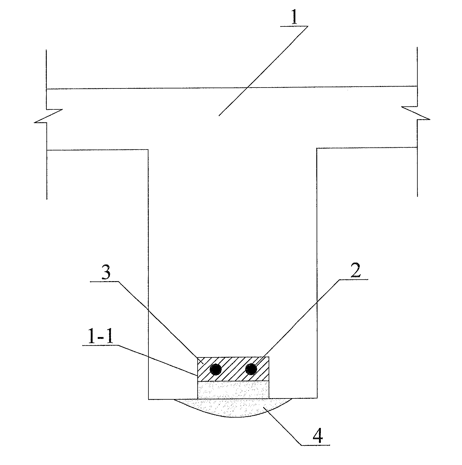
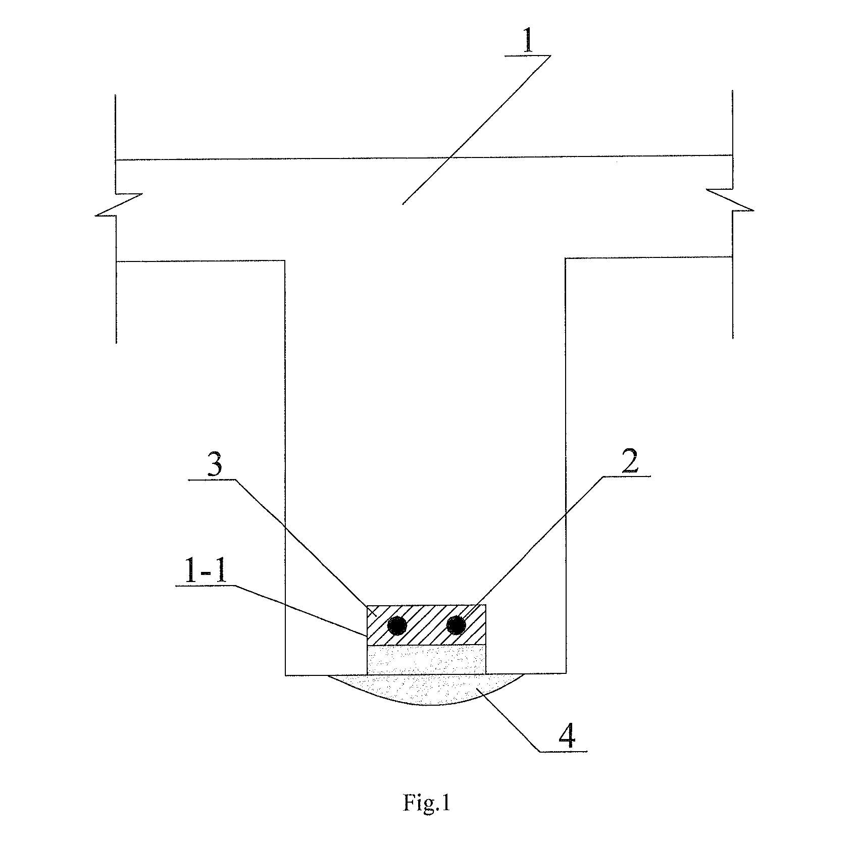
[0011]As shown in FIG. 1, in this example, the concrete structure member strengthened with prestressed FRP bar comprises a concrete structure member body 1 and prestressed FRP bar 2. A groove 1-1 is made on the bottom surface of the concrete structure member body 1, and the prestressed FRP bar 2 is arranged in the groove 1-1.

[0012]Preferably, the depth and the width of the groove 1-1 are equal to each other, and are 1.5 times of the diameter of the prestressed FRP bar 2.

[0013]An epoxy resin cladding layer 3 is arranged in one part of the groove 1-1. The epoxy resin cladding layer 3 is arranged around the prestressed FRP bar 2 and surrounds the FRP bar 2. A polymer-concrete thickening layer 4 is arranged in the rest part of the groove 1-1. After the polymer-concrete thickening layer 4 fills up the rest part of the groove 1-1, the bottom surface of the concrete structure member body 1 can be shaped as dome or plane.

example 2

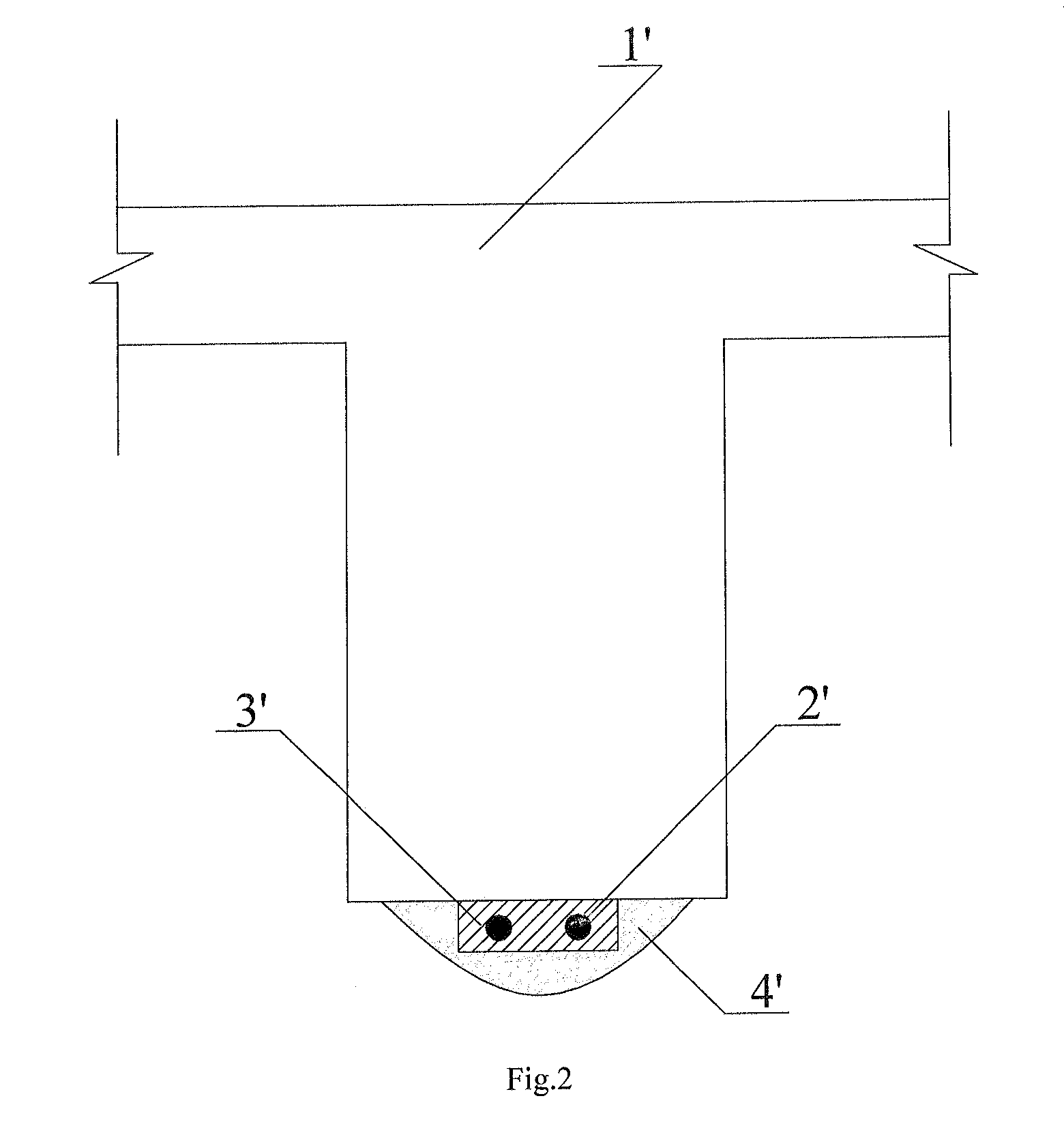
[0014]As shown in FIG. 2, in this example, the concrete structure member strengthened with prestressed FRP bar comprises a concrete structure member body 1′ and prestressed FRP bar 2′. The prestressed FRP bar 2′ is arranged on the bottom surface of the concrete structure member body 1′. An epoxy resin cladding layer 3′ is arranged around the prestressed FRP bar 2′ and surrounds the FRP bar 2′. A polymer-concrete thickening layer 4′ is arranged outside of the epoxy resin cladding layer 3′, to bond the prestressed FRP bar 2′ and the epoxy resin cladding layer 3′ to the bottom surface of the concrete structure member body 1′.

[0015]As shown in FIG. 3, under the same prestress condition, curve A represents a case in which both the cladding layer and the thickening layer are made of epoxy resin; curve B represents a case in which both the cladding layer and the thickening layer are made of polymer-concrete; curve C represents a case in which the cladding layer is made of epoxy resin while...


PUM

PropertyMeasurementUnit
diameteraaaaaaaaaa
weightaaaaaaaaaa
strengthaaaaaaaaaa

Abstract

A concrete structure member strengthened with prestressed FRP elements includes a concrete structure body and a prestressed FRP element arranged on the former. An epoxy resin overlay surrounding the prestressed FRP element is provided to wrap it up, and a polymer concrete supplemental layer is provided outside the epoxy resin overlay. The concrete structure member can uniformly and effectively transfer the stress from the prestressed FRP element.

Description

FIELD OF THE INVENTION[0001]The present invention relates to a concrete structure member, in particular to a concrete structure member strengthened with prestressed FRP bars.BACKGROUND OF THE INVENTION[0002]Fiber reinforced polymer (FRP) bars are featured with light weight, high strength, and high corrosion resistance, etc., and have been widely applied in building projects to substitute steel strands and steel bars. Concrete structures strengthened with embedded FRP bars are one of the main applications, in which FRP bars are put into preformed grooves on the surface of structure, and a binding material is poured into the grooves, so that the FRP bars and the structure form a whole, so as to improve structural properties. Prestressing technique is introduced subsequently, to give full play to the high strength effect of FRP bars. Such a technical application of FRP bars can effectively improve rigidity, bending resistance, and shear resistance bearing capacity of structures. Howeve...

Claims


Application Information

Patent Timeline
Patent Type & Authority Applications(United States)
IPC IPC(8): E04C5/07B32B3/30B32B13/12
CPCE04G23/0218B32B3/30Y10T428/24612E04C5/073B32B13/12E04G2023/0255Y10T428/249921E04C5/085
Inventor WU, ZHISHENWU, GANGIWASHITA, KENTAROJIANG, JIANBIAOZHANG, MIN
Owner SOUTHEAST UNIV
Learn More