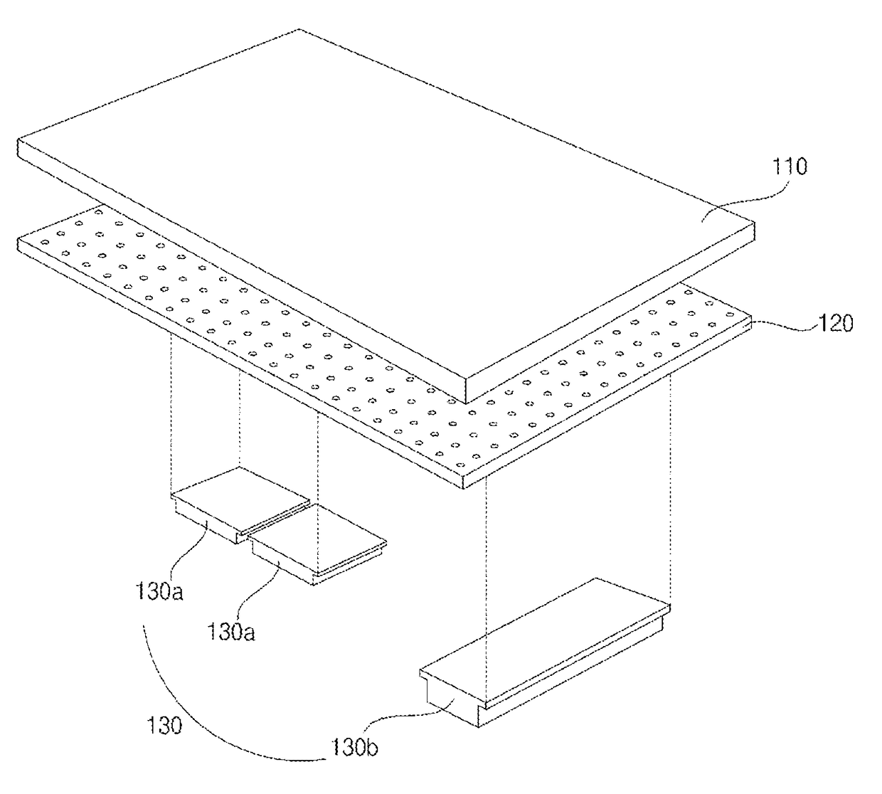
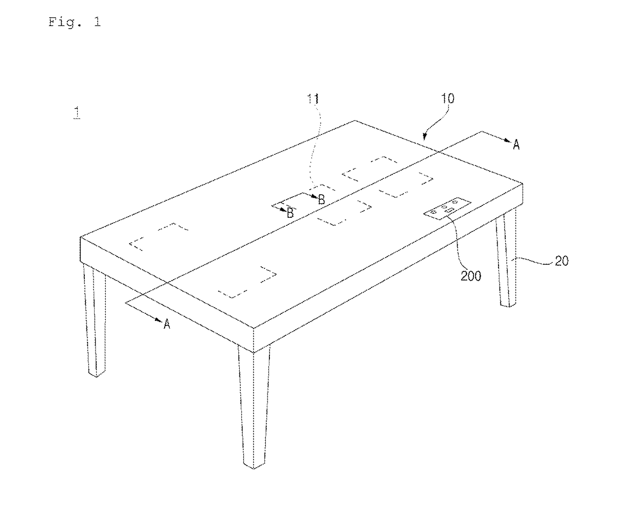
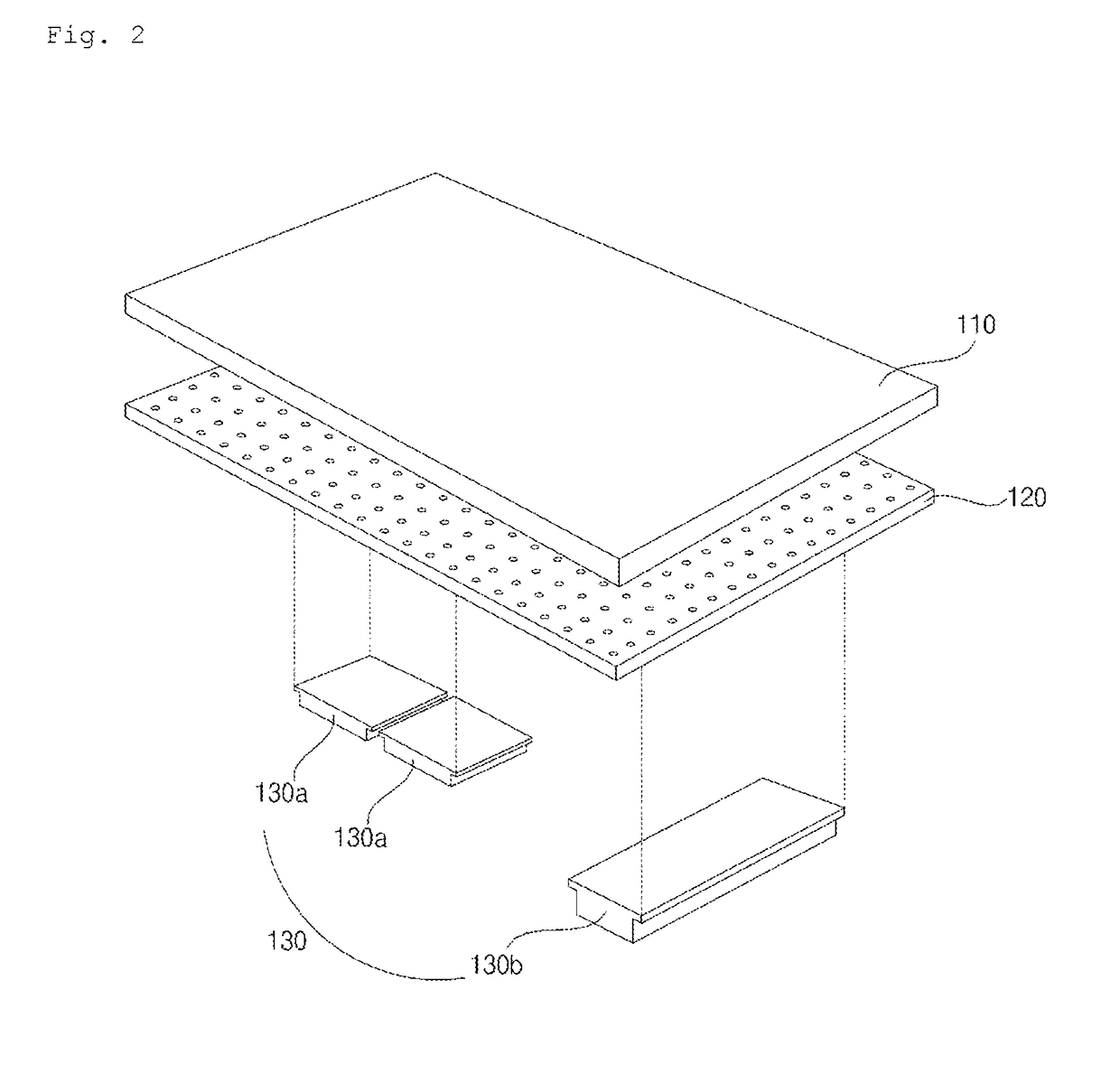
Table top

a table top and table top technology, applied in the field of table tops, can solve the problems of inability to change the heating region, the position cannot be readily changed, and the printing may be damaged, so as to achieve the effect of convenient disposed

a table top and table top technology, applied in the field of table tops, can solve the problems of inability to change the heating region, the position cannot be readily changed, and the printing may be damaged, so as to achieve the effect of convenient disposed

US20180310367A1Active Publication Date: 2018-10-25LG ELECTRONICS INC

Image

  • Table top
  • Table top
  • Table top

Examples


Embodiment Construction

[0033]Hereinafter, embodiments of the present disclosure will be described in detail with reference to the accompanying drawings.

[0034]Advantages and features of the present invention and methods for achieving those of the present invention will become apparent upon referring to embodiments described later in detail with reference to the attached drawings. However, embodiments are not limited to the embodiments disclosed hereinafter and may be embodied in different ways. The embodiments are provided for perfection of disclosure and for informing persons skilled in this field of art of the scope of the present invention. The same reference numerals may refer to the same elements throughout the specification.

[0035]Spatially-relative terms such as “below”, “beneath”, “lower”, “above”, or “upper” may be used herein to describe one element's relationship to another element as illustrated in the Figures. It will be understood that spatially-relative terms are intended to encompass differe...


PUM


Abstract

Provided is a table top including: an upper plate, which is constituted by a plate-shaped non-magnetic member so as to support an electronic or cooking device placed thereon; an energy supply module, which is disposed under the upper plate so as to supply energy to the electronic or cooking device; at least one light source configured to generate light; and at least one light-transmissive portion, which is provided in the upper plate and through which the light generated by the light source is transmitted; and at least one light guide configured to guide the light, generated by the light source, to the light-transmissive portion, wherein the at least one light guide allows at least a portion of the light, generated by the light source, to be emitted upward from the upper plate through the light-transmissive portion.

Description

CROSS-REFERENCE TO RELATED APPLICATION[0001]This application is a continuation of U.S. application Ser. No. 15 / 471,198, filed on Mar. 28, 2017, which claims the priority benefit of Korean Patent Application No. 10-2016-0037038, filed on Mar. 28, 2016 in the Korean Intellectual Property Office, the disclosures of which are incorporated herein by reference.BACKGROUND OF THE INVENTION1. Field of the Invention[0002]The present disclosure relates to a table top.2. Description of the Related Art[0003]A table top, which is generally used as a table at home and restaurants, was conventionally used to support objects.[0004]Recently, such table top is used in multipurpose applications, with a cooking device or an electronic device being provided thereon to make better use of space.[0005]Particularly, there has been released a table top, which has an induction heating device for heating metal cooking equipment by induction heating.[0006]As the table top is used in many applications and is inst...

Claims


Application Information

Patent Timeline
25 Oct 2018
Publication
US20180310367A1
IPC
H05B6/12; F24C15/10
CPC
H05B2213/07; H05B2213/05; F24C15/10; H05B6/1218; H05B6/1245; G02B6/0065; G02B6/0055; G02B6/0035
Inventors
NAM, HYEUNSIK; KIM, WANSOO