Device case closing structure

a device case and closing structure technology, applied in the direction of electrical/fluid circuits, electrical apparatus casings/cabinets/drawers, vehicle components, etc., can solve the problems of reducing ventilation performance, complex structure, etc., and achieve the effect of reducing ventilation performance, and simplifying the device case closing structur

Active Publication Date: 2018-11-01
SUMITOMO WIRING SYST LTD
View PDF6 Cites 2 Cited by
  • Summary
  • Abstract
  • Description
  • Claims
  • Application Information

AI Technical Summary

Benefits of technology

[0005]According to this configuration, the seal cover doubles as a filter for ventilation and the vent hole doubles as the bolt receiving portion for receiving the tip part of the bolt for connecting the device terminal portion and the connection terminal. Thus, the device case closing structure can be simplified.
[0006]The ventilation member may be arranged to close the vent hole from the surface facing out of the device case on the cover body, and the cover body

Problems solved by technology

The sealed case has a mounting hole and a filter allowing the passage of air, but not allowing the passage of water is mounted in the mounting hole.
However, in the above configuration

Method used


Image

  • Device case closing structure
  • Device case closing structure
  • Device case closing structure

Examples


case 10

[0015][Device Case 10]

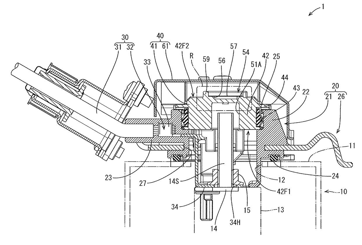
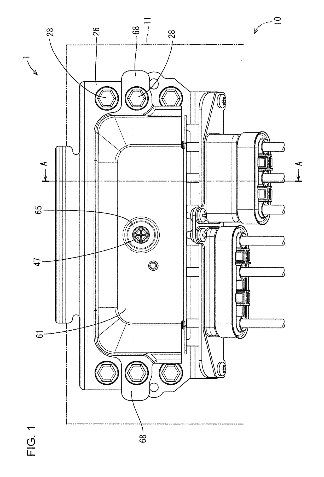
[0016]The device case 10 is installed in a vehicle to accommodate a device, such as a motor or an inverter. This device case 10 is a metal box having an electromagnetic shielding function and includes a case wall 11 separating between an internal space and an external space. The case wall 11 includes a connector mounting hole 12 penetrating from an inwardly facing surface to an outwardly facing surface of the device case 10, and the shield connector 20 is assembled with this case wall 11 while being aligned with the connector mounting hole 12. Terminal blocks 13 including device terminals connected to the device are arranged inside the device case 10. The stud bolt 14 projects from each terminal block 13.

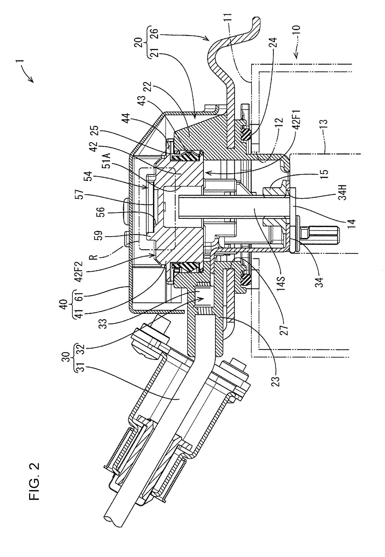
[0017][Shield Connector 20]

[0018]As shown in FIG. 2, the shield connector 20 includes a housing 21 for holding wires with terminals 30, and a fixing plate 26.

[0019]Each of the wires with terminals 30 has a general configuration that a terminal fitting 32 is con...


PUM


Abstract

A device case closing structure (1) has a shield connector (20) with a work opening (25) and is assembled with a device case (10) while holding terminal fittings (32). A seal cover (40) is assembled with the shield connector (20) for closing the work opening (25). Stud bolts (14) connect the terminal fittings (32) with terminal blocks (13) in the device case (10). The seal cover (40) includes a cover body (41) to be fit to the shield connector (20). The cover body (41) includes a vent hole (55) and a breathable film (57) having waterproofness and breathability is arranged to close the vent hole (55). A part of the vent hole (55) serves as a bolt receiving portion (51) for receiving a tip of the stud bolt (14) inside.

Description

BACKGROUNDField of the Invention[0001]This specification relates to a device case closing structure.Description of the Related Art[0002]Japanese Unexamined Patent Publication No. 2001-168545 discloses an electrical device to be installed in an automotive vehicle or the like. The electrical device is accommodated in a case that is provided with a connector, a terminal block for connection of the electrical device and an external device. The electrical device generally is required to be waterproof, and thus the case is of a sealed type. The sealed case has a mounting hole and a filter allowing the passage of air, but not allowing the passage of water is mounted in the mounting hole. The filter alleviates a pressure difference between the inside and outside of the case generated by an ambient temperature variation or the like while maintaining waterproofness.[0003]However, in the above configuration, a structure is complicated by providing the filter.SUMMARY[0004]A device case closing ...

Claims


Application Information

Patent Timeline
IPC IPC(8): B60R16/023B60R16/02
CPCB60R16/0239B60R16/0215H05K5/065H05K5/0247H05K5/0215H05K5/06
Inventor UMEMURA, KENJI
Owner SUMITOMO WIRING SYST LTD
Why Eureka
Try Eureka