
Shoe, a patch and a method for preventing ankle injuries

a technology of ankle injuries and ankle sprains, applied in the field of shoes, can solve the problems of lateral sprain, lateral sprain, frequent fractures, etc., and achieve the effects of reducing friction, reducing friction, and increasing lifetim

Active Publication Date: 2018-11-08
SPRAINO IP APS
View PDF14 Cites 12 Cited by
  • Summary
  • Abstract
  • Description
  • Claims
  • Application Information

AI Technical Summary

Benefits of technology

The invention proposes a shoe that can reduce friction and prevent ankle injuries in humans. It achieves this by mounting a sliding shoe on the foot and promoting sliding between the shoe and ground in case of unbalanced motion of the foot. The shoe has areas of reduced friction that provide different coefficients of friction in different directions. This results in adequate friction for certain types of movements, while decreasing the risk of injury for the wearer. The reduced friction areas can be provided by using poly-directional friction, such as fibers that bend preferentially along certain directions or ripples along certain directions.

Problems solved by technology

In these patients a part of the mechanism that causes re-injury is an erroneous sensation of the position of the ankle joint in plantar flexion 30° / inversion 20° whereby the joint can be more plantar-flexed and inverted when landing thus creating a risk of lateral distortion.
This results in a lateral sprain (distortion) but fractures also occur frequently.
The injuries can also be treated with taping or semi rigid braces but both methods have significant limitations as they provide a limited support especially for repeated injuries and often degrades freedom of movement for the wearer.
Also, the restricting effect of tape is lost after varying periods of exercise (Am J Sports Med November 2010 vol.

Method used


Image

  • Shoe, a patch and a method for preventing ankle injuries
  • Shoe, a patch and a method for preventing ankle injuries
  • Shoe, a patch and a method for preventing ankle injuries

Examples


Embodiment Construction

[0048]Preferred embodiments of the invention will now be described with reference to the accompanying drawings, wherein:

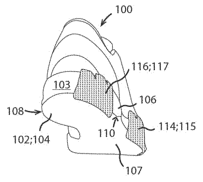
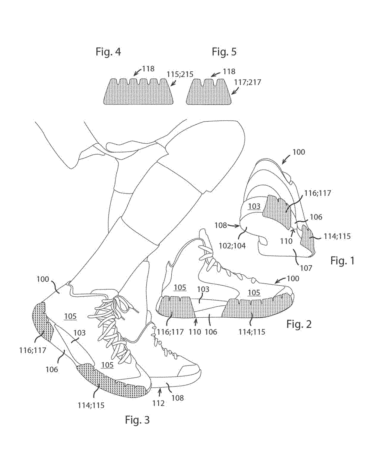
[0049]FIGS. 1 and 2 show first and second views of an embodiment of a shoe according to the invention;

[0050]FIG. 3 shows the shoe of FIGS. 1 and 2 mounted to a foot of a human wearer;

[0051]FIGS. 4 and 5 show first and second embodiments of a patch according to the invention;

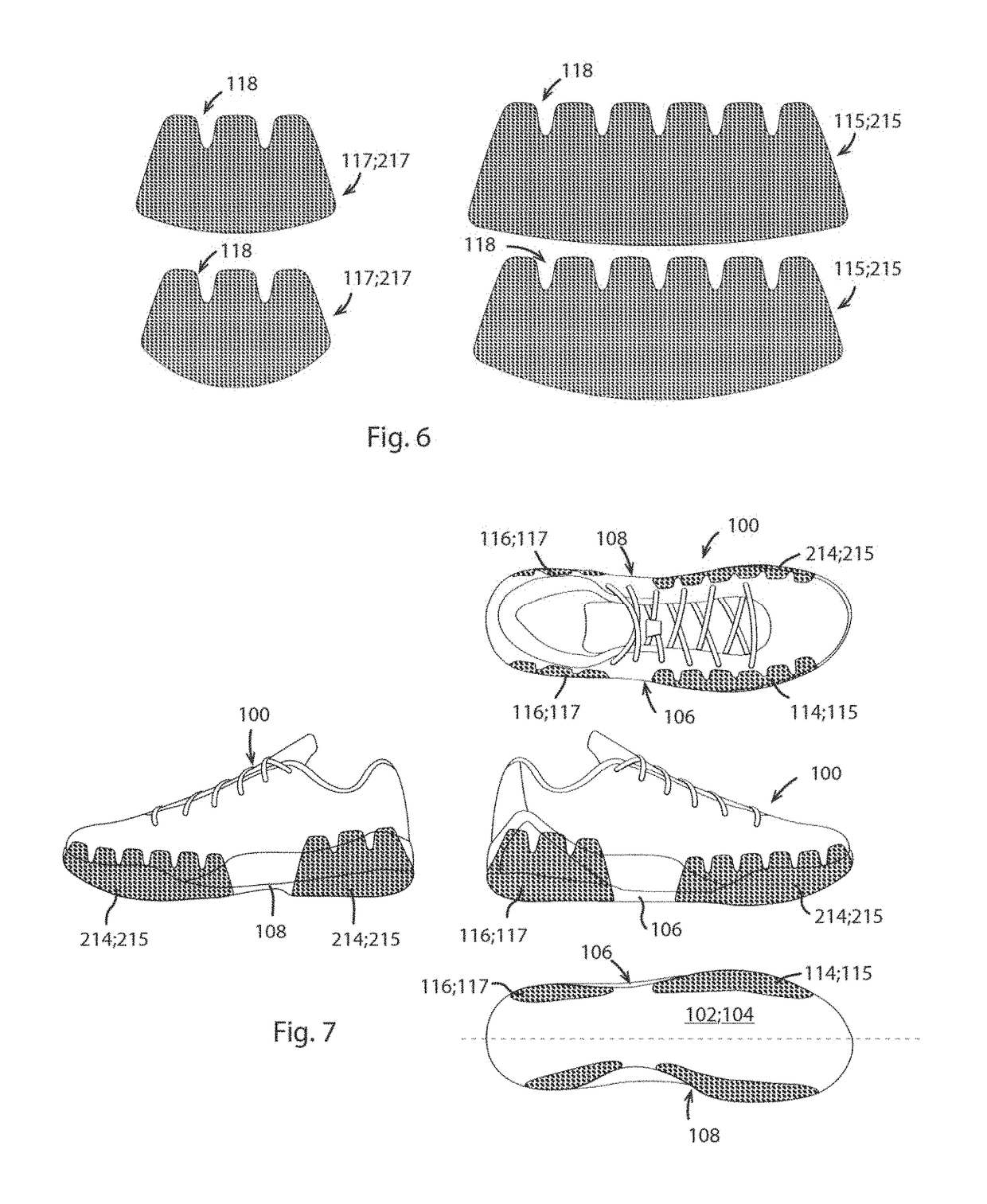
[0052]FIG. 6 illustrates alternative embodiments of patches according to the invention;

[0053]FIG. 7 illustrates an embodiment of a shoe comprising a patch according to the invention;

[0054]FIG. 8 generally depicts various configurations of a shoe according to the invention;

[0055]FIG. 9 illustrates a further embodiment of a shoe according to the invention.

[0056]FIG. 10 illustrates an alternative embodiment of a patch according to the invention.

[0057]FIGS. 11 and 12 illustrate alternative embodiments of patches according to the invention.

[0058]FIG. 13 illustrates alternative embodiments of scaled p...


PUM


Abstract

A shoe for preventing ankle injuries comprises a sole with a ground-engaging surface, and lateral and medial edges associated with respective lateral and medial connecting portions interconnecting and extending between the ground-engaging surface and the lateral and medial edges. At least one of the connecting portions defines a surface area of reduced friction provided, e.g., in the form of retrofitted patches, which are circumferentially surrounded by adjacent surface areas having a relatively high coefficient of friction. Friction is differentiated in different areas of those parts of the shoe which are implicated in injury mechanisms, and injuries may thus be prevented in the recovery phase after injury, and primary prophylaxis may be achieved. The area of reduced friction reduces the ability of the wearer's foot to rotate relative to ground when the load of the wearer's body is shifted towards or lands near the edge of the shoe.

Description

TECHNICAL FIELD[0001]The present invention generally relates to a shoe tailored to reduce the risk of ankle injuries, typically a sports shoe. The invention also relates to a patch for back-fitting to an existing shoe with a view to preventing ankle injuries. Further the invention relates to a method of preventing ankle injuries in a human wearing a shoe.BACKGROUND OF THE INVENTION[0002]It has been estimated that ankle injuries account for 15-30% of all injuries in sport. In the United States alone 23,000 injuries are thought to happen every day. The average treatment cost of sprains and strains is $2294 in the US (ASPE Issue Brief, March 2014). Based on these numbers and assuming most ankle injuries are sprains and strains the estimated annual treatment cost for ankle injuries amounts to 3-6 billion dollars. This cost does not include lost productivity caused by injuries, which can be very significant especially for professional high income athletes and very high on a societal leve...

Claims


Application Information

Patent Timeline
Patent Type & Authority Applications(United States)
IPC IPC(8): A43B13/26A43B7/19A43B7/20A43C13/06
CPCA43B13/26A43B7/19A43B7/20A43C13/06A43C13/00A43B5/005A43B13/22
Inventor GRONLYKKE, THOR BUCH
Owner SPRAINO IP APS
Learn More