High retention force serviceable plug-on joint assembly

Active Publication Date: 2018-11-08
NEAPCO INTPROP HLDG LLC
View PDF0 Cites 4 Cited by
  • Summary
  • Abstract
  • Description
  • Claims
  • Application Information

AI Technical Summary

Benefits of technology

[0008]It would be desirable to provide a robust plug-on CV joint configured for maximized axial retention

Problems solved by technology

Disadvantageously, the snap rings used to axially retain or lock the CV joint to the powertrain or final drive components are entirely covered and not easily accessible after assembly.
As a result, the snap ring is not easily accessible for disassembly or disen

Method used


Image

  • High retention force serviceable plug-on joint assembly
  • High retention force serviceable plug-on joint assembly
  • High retention force serviceable plug-on joint assembly

Examples


example

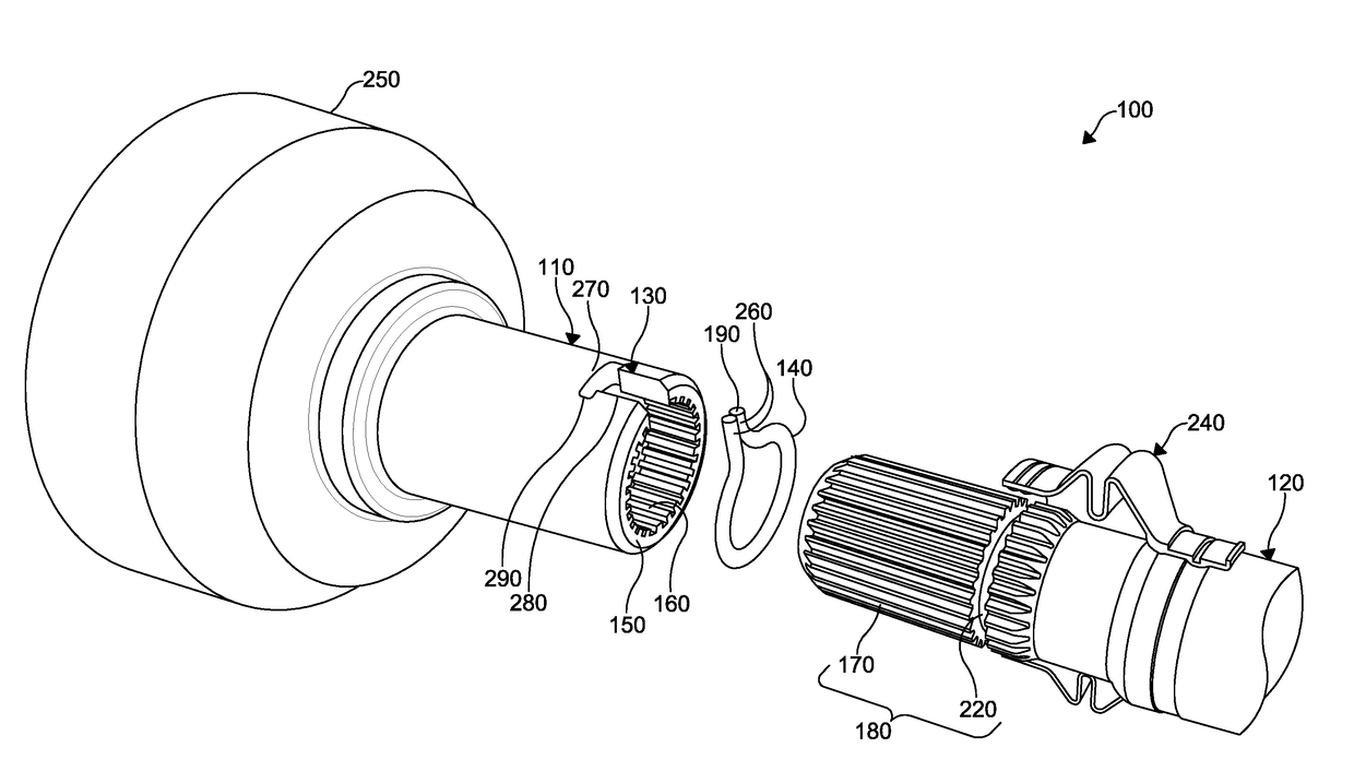
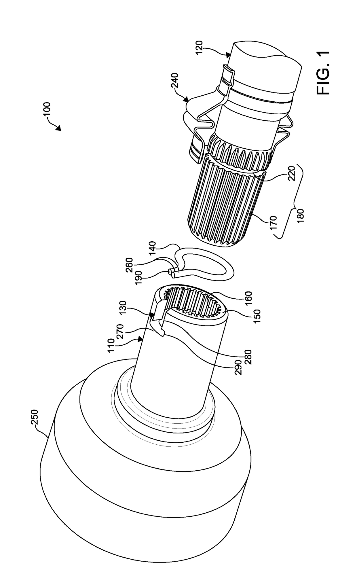
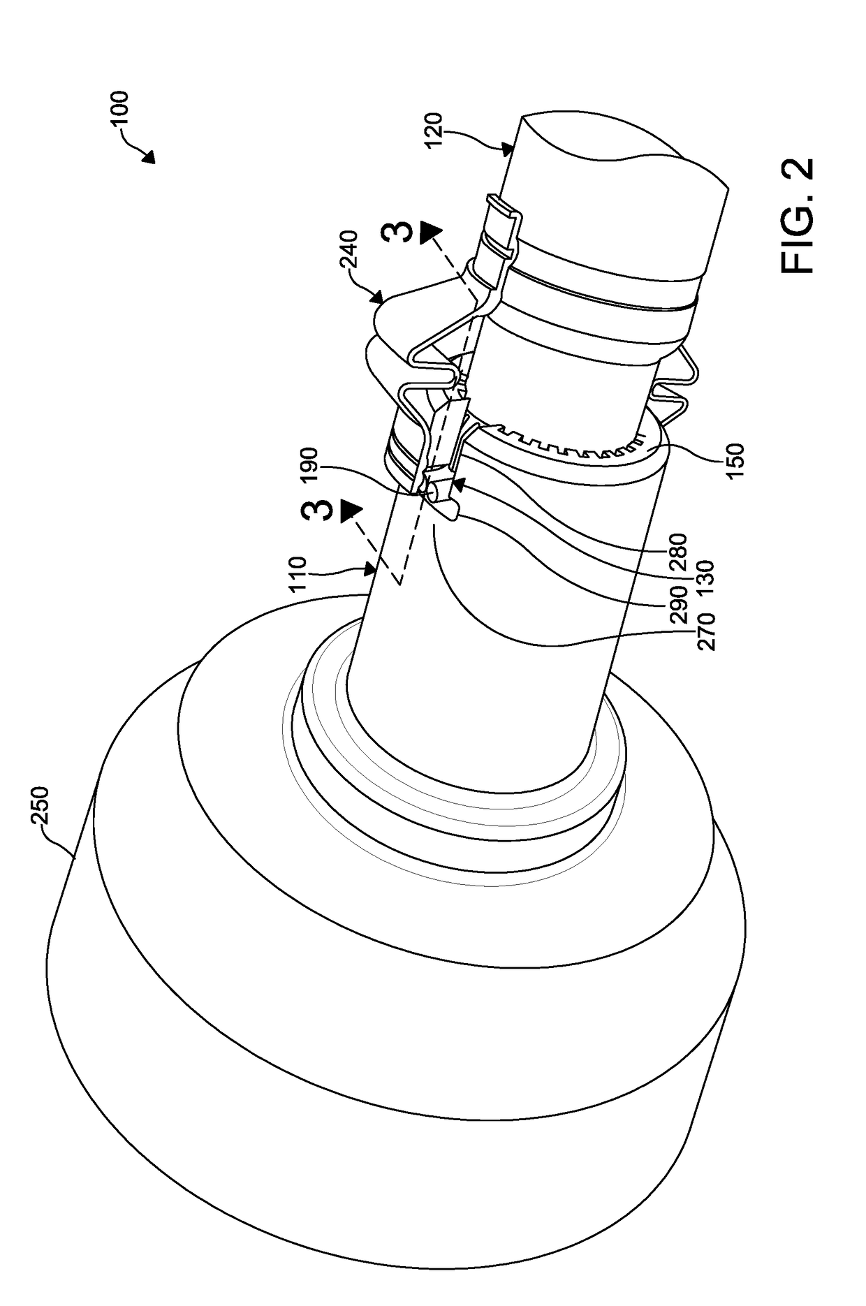
[0029]With reference now to FIGS. 1-3, an embodiment of a joint assembly according to the present technology is shown at 100.

[0030]The joint assembly 100 includes a first member 110, a second member 120, a window 130, and a retaining ring 140. The first member 110 has an open end 150 and a first plurality of splines 160 formed within the open end 150. The second member 120 has a second plurality of splines 170 formed thereon. A portion 180 of the second member 120 is disposed within the open end 150 of the first member 110, where the second plurality of splines 170 engages the first plurality of splines 160 to provide a coupling of the second member 120 to the first member 110. The window 130 is formed within the first member 110 where the portion 180 of the second member 120 is disposed within the first member 110. The retaining ring 140 is configured to retain the coupling of the second member 120 to the first member 110. A portion 190 of the retaining ring 140 is accessible throu...


PUM


Abstract

A joint assembly includes a first member having splines formed therein. A second member includes splines formed thereon and is coupled to the first member. The splines of the first member engage the splines of the second member. An access window is formed on the first member. A ring retains the first member to the second member. A portion of the ring is accessible through the access window, where the ring can be manipulated to release the first member from the second member.

Description

CROSS-REFERENCE TO RELATED APPLICATIONS[0001]This application claims the benefit of U.S. Provisional Application No. 62 / 500,821, filed on May 3, 2017. The entire disclosure of the above application is incorporated herein by reference.FIELD[0002]The present technology relates to joint assemblies, particularly to a propeller shaft constant velocity joint with a plug-on interface that provides a high retention force and service access for disassembly thereof.INTRODUCTION[0003]This section provides background information related to the present disclosure which is not necessarily prior art.[0004]Joint assemblies, including various universal and constant velocity joints, are common components in automotive vehicles for applications requiring a transmission of torque through an angle. Universal joints can be used to join portions of a driveshaft. Constant velocity joints (CV joints or CVJs) are typically used to transmit torque at an angle from a powertrain transmission (transmission or fo...

Claims


Application Information

Patent Timeline
IPC IPC(8): F16D1/116F16B21/18
CPCF16D1/116F16B21/18F16D2001/103F16B21/186F16D2003/22326
Inventor HOPSON, MICHAEL WALTERSRINIVASAN, ARVINDKINSELLA, MICHAEL PETER
Owner NEAPCO INTPROP HLDG LLC
Why Eureka
Try Eureka