Sterilant system

a sterilization system and system technology, applied in the direction of liquid transfer devices, instruments, volume meters, etc., can solve the problems of not being as effective as chlorine dioxide and not always convenient to mix up batches of solutions, and achieve the effect of stable compound

Active Publication Date: 2014-09-23
TRISTEL PCL
View PDF17 Cites 2 Cited by
  • Summary
  • Abstract
  • Description
  • Claims
  • Application Information

AI Technical Summary

Benefits of technology

[0010]By dispensing each reagent in a foam the resulting sterilising composition provides good surface contact with minimal splashing. The foam may formulated to be tenacious and form-retaining so that it resists flow when applied to a vertical or sloping surface such as the plastic-walled tent of a hospital isolation unit.
[0011]Moreover, where the reagents react to produce a volatile sterilant, such as chlorine dioxide, we have found that the concentration of volatile sterilant in the air is reduced compared to a corresponding non-foamed mixture. This enables the use of higher concentrations of reagents than with a liquid system.
[0012]Because both reagents are dispensed in separate foams before they react together the reaction products are formed within the foam. This maximises retention of those products in the foam and on a surface to which they are applied, and minimises losses through evaporation.
[0022]In a preferred embodiment, a humectant is included in at least one of the first and second parts, preferably in both parts. Humectants serve to reduce the rate of evaporation of components and improve product feel if direct skin contact is involved. We have found that the use of a humectant reduces the volatility of chlorine dioxide, which reduces the odour of chlorine dioxide and prolongs the life of the activated mixture. Non-limiting examples of suitable humectants include sodium lactate and polyols, for example glycerine, sorbitol, propylene glycol, diethylene glycol and ethylene glycol. The humectant may be present in any desired amount, particularly from about 0.1 to 50% by weight, notably from about 0.5 to 10%, preferably from about 1 to 3%.

Problems solved by technology

It is not always convenient to mix up batches of solutions for use in sterilising equipment.
For wiping down (rather than thoroughly cleaning inside and out) of endoscopes and probes, wipes of alcohol, general-purpose detergent, or soapy water are generally used, but these are not as effective as chlorine dioxide.

Method used


Image

  • Sterilant system
  • Sterilant system
  • Sterilant system

Examples


Embodiment Construction

[0037]In this specification, all parts are by weight unless otherwise indicated.

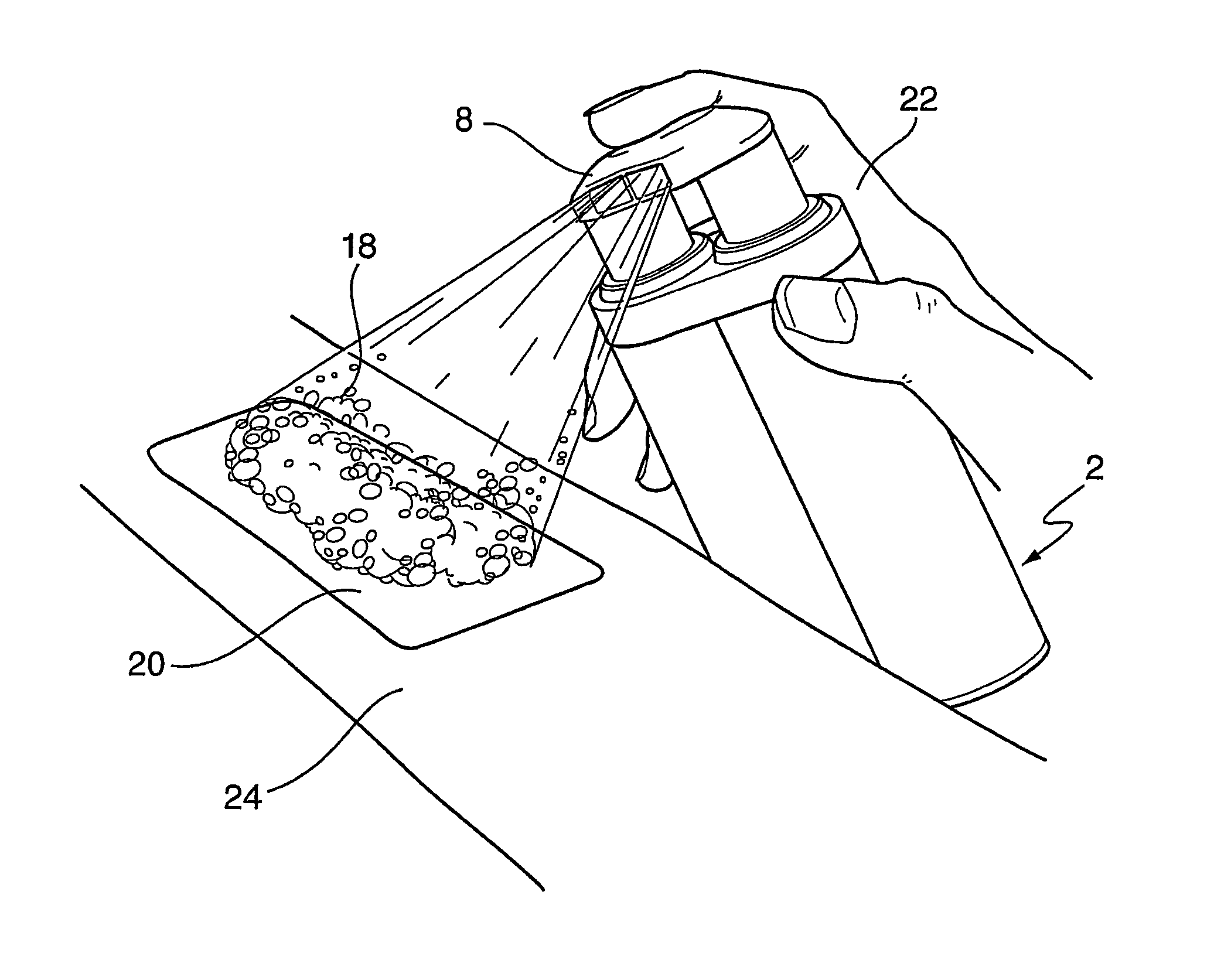
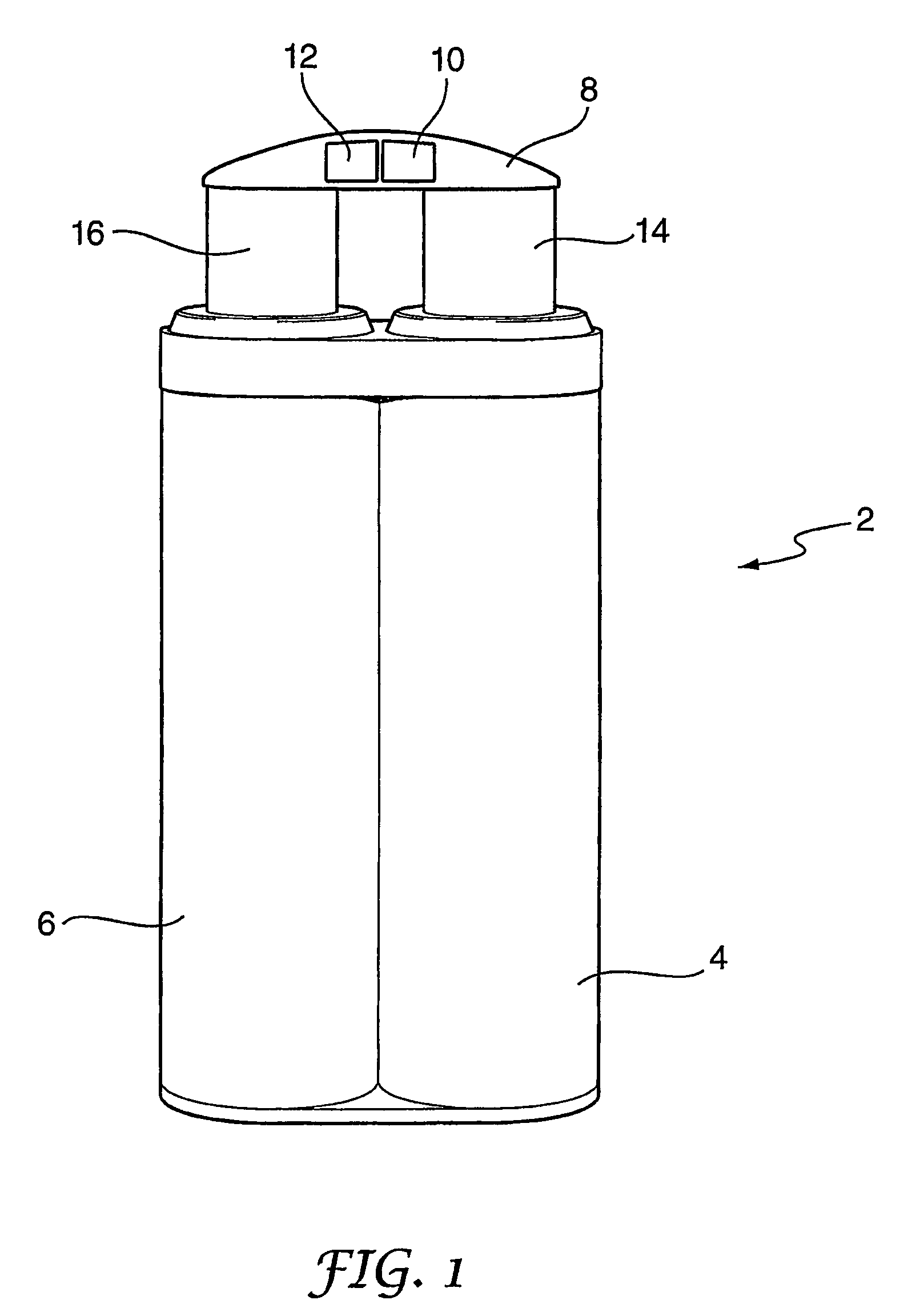
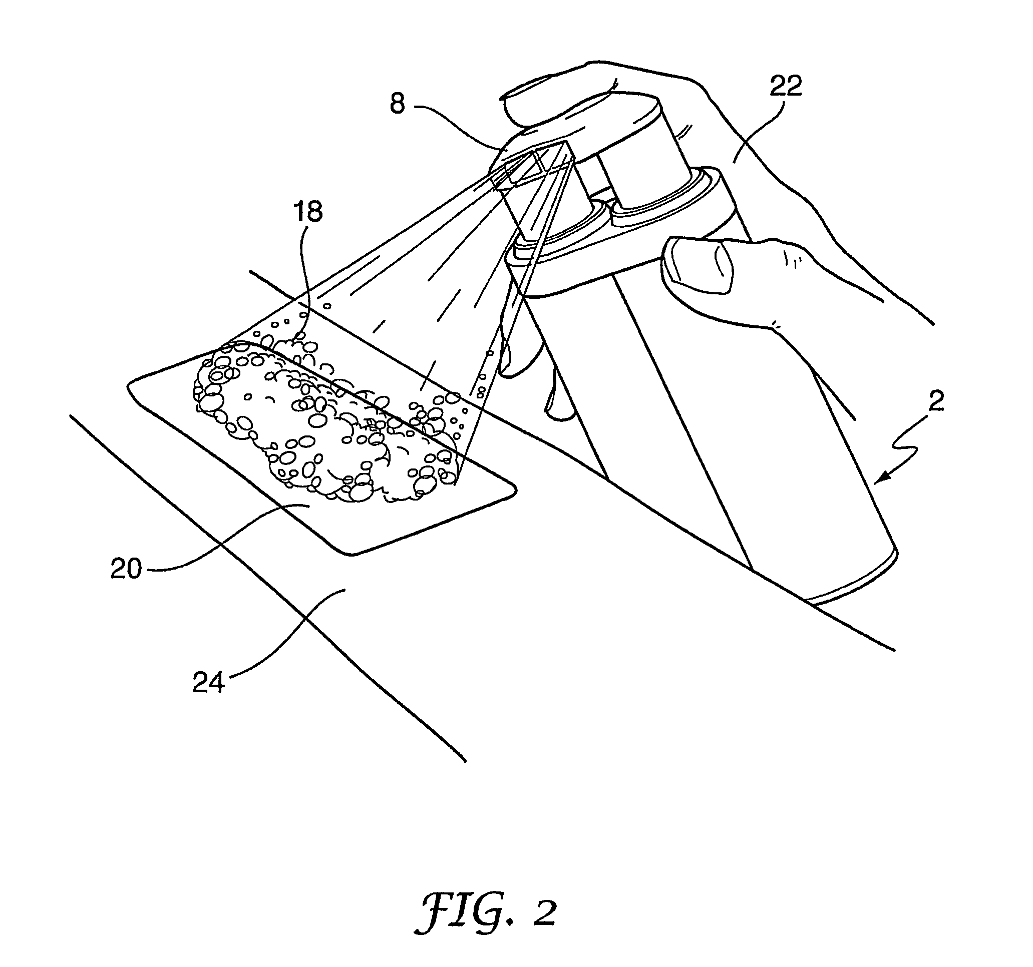
[0038]The Dual Foamer foam dispenser 2 shown in FIG. 1 (from Airspray International BV) has a first dispenser chamber 4 clipped to a second dispenser chamber 6. The chambers 4, 6 are part of two small foam pump systems which dispense their contents as foams when respective piston members 14, 16 are depressed. Operation of a single actuator 8 depresses both piston members 14, 16, causing a volume of liquid (in this example, 0.8 ml) to be pumped from each chamber 4, 6 simultaneously and combined with air to form a foam. The liquid from chamber 4 is turned into a first foam and the liquid from chamber 6 is turned into a second foam. The first and second foams are dispensed via respective separate nozzle orifices 10, 12 in the actuator 8.

[0039]In the present example, the first dispenser chamber 4 is filled with a liquid (first part) which comprises deionised water containing 0.75% of a first reagent (sodium ...


PUM

PropertyMeasurementUnit
volumeaaaaaaaaaa
colouraaaaaaaaaa
pHaaaaaaaaaa

Abstract

A two-part sterilant system comprises: (a) a first part comprising a first reagent in an aqueous medium having a first foam promoter dissolved therein and contained in a first dispenser whereby it may be dispensed as a first foam; and (b) a second part which comprises a second reagent in an aqueous medium having a second foam promoter dissolved therein and contained in a second dispenser whereby it may be dispensed as a second foam; wherein the first reagent and the second reagent will react to provide a sterilizing composition when the first foam is mixed with the second foam.

Description

BACKGROUND OF THE INVENTION[0001]1. Field of the Invention[0002]The present invention relates to a sterilant system and method for sterilising surfaces.[0003]2. Description of the Prior Art[0004]Two-part sterilising solutions are used in applications where the active sterilising ingredient is unstable over time. The solution is therefore prepared in situ shortly before it is to be used. A particularly important sterilising agent is chlorine dioxide (ClO2), which may be formed from mixtures of various reagents including: chlorite and acid; chlorate, peroxide and acid; and chlorite, hypochlorite, and a suitable buffer. Chlorine dioxide has excellent sterilising and bactericidal properties, and oral ingestion in man and animals has been shown to be relatively safe.[0005]ClO2 gas is a respiratory and eye irritant so its concentration in air needs to be controlled at safe levels. The occupational exposure standard limit (OES) in the UK is set at 0.3 ppm (0.9 mg / m3) as a 15 minute short t...

Claims


Application Information

Patent Timeline
Patent Type & Authority Patents(United States)
IPC IPC(8): A61L2/00B65D88/54A01N25/16A01N59/00A61L2/22A61L2/235C01B11/02
CPCA61L2/22A01N59/00A61L2/0082C01B11/023A01N25/16C01B11/024A01N2300/00A61L2/16A61L15/00
Inventor GREEN, BRUCE, PHILIP
Owner TRISTEL PCL
Why Eureka
Try Eureka