A cable stripping tool for electrical cables

a technology for electrical cables and cable ties, which is applied in the direction of cables, insulated conductors, coupling device connections, etc., can solve the problems of unsatisfactory cable ties, inability to provide smart meter casings, and inability to provide cable ties, etc., and achieve the effect of safe fitting into the connector

Inactive Publication Date: 2018-11-08
HELLERMANN TYTON LTD
View PDF18 Cites 2 Cited by
  • Summary
  • Abstract
  • Description
  • Claims
  • Application Information

AI Technical Summary

Benefits of technology

[0009]The radial spacing of the blade edges in the cutting position allows the first cutting blade to be arranged to cut through both the inner and outer sheathes of the cable to the radial depth of the core while the second blade cuts through only the outer sheath. As the blades are axially spaced, once the full cut has been made the inner sheath is cut at the axial position of the first blade, exposing beyond it the inner core. The inner sheath extends to a greater axial length than the outer sheath, which is cut at the axial position of the second blade at a position spaced further along the cable. This forms a stepped arrangement in which the diameter of the cable steps down to that the of the outer surface of the inner sheath at a first axial position, and then steps down to a second diameter corresponding to the diameter of the inner core. The ability of the tool to rotate about the around the rotational axis enables the cutting blades to cut around the entire circumference of the cable once the blades have made the initial insertion on movement to the cutting position.
[0010]The stepped configuration of the stripped cable conforms to the inner configuration of the cable markers. The step defined by the cut between the outer surface of the outer sheath and the outer surface of the inner sheath that exposes the inner sheath locates and abuts a first abutment surface within the cable marker. The second step defined by the cut through the inner sheath to the core seats against a second abutment surface within the marker, inwardly of the first abutment surface. This double stepped arrangement within the marker makes it extremely difficult if not impossible to access the core of the cable through the cable marker, thereby ensuring the electrical core is unable to be accidentally or intentionally contacted once the connection portion of the cable marker is inserted into and connected to the housing of electrical meter. The two step arrangement also ensures that the point along the cable at which the core is exposed is spaced inwardly into the cable marker / connector passed the first abutment surface. The arrangement of the blades of the stripping tool ensures a consistent, clean and reproducible cut that ensures the cable always closely and safely fits into the connector. This is especially important where the tool may be used by a non-skilled or newly trained operator as it allows them to produce the required finish on the cable without difficulty.

Problems solved by technology

The traditional means of metering electricity usage provides a cumulative measure of consumption that doesn't allow the user to appreciate the varying levels of usage over the time.
As electrical cables can vary is diameter, it is not possible to provide a smart meter casing having a universal opening that satisfies both these requirements.
The current practice of marking cables using cable ties is undesirable as it generates material wastage and debris at the point of use.
In addition the rotational position of the cable ties about the cables is not able to be fixed, which prevent the ties from being readable.
Furthermore it is also not possible to remove and relocate cable ties as removal requires the ties to be cut.

Method used


Image

  • A cable stripping tool for electrical cables
  • A cable stripping tool for electrical cables
  • A cable stripping tool for electrical cables

Examples


Embodiment Construction

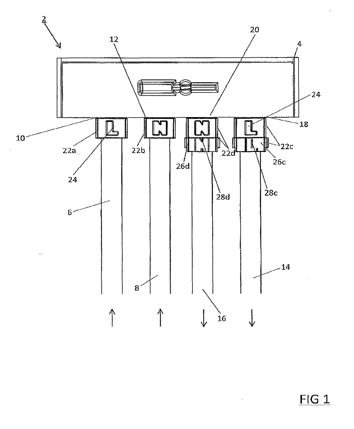
[0057]Referring to FIG. 1, a smart electrical meter 2 comprises an enclosure 4 that houses and contains metering means for monitoring electrical consumption and for transmitting that information to the utility company and to the consumer. While the invention is described for use with a smart meter, it will be appreciated that it is not limited to this application and may be used in any application requiring the safe connection of electrical cables into an enclosure. The metering means comprises electrical connection terminals which connect to incoming and outgoing live and neutral electrical cables. The incoming mains supply comprises a live cable 6 and neutral cable 8. The incoming live 6 and neutral 8 enter the meter enclosure 4 through inlet openings 10 and 12 respectively and are secured to the terminals within the enclosure. The outgoing live cable 14 and neutral cable 16 leave the enclosure 4 via outlet openings 18 and 20 and connect to the power circuits of the property.

[0058...


PUM

PropertyMeasurementUnit
diameteraaaaaaaaaa
diameteraaaaaaaaaa
diametersaaaaaaaaaa

Abstract

A cable stripping tool for use with electrical cables comprising an inner core and at least one outer sheath. The cable stripper includes a body including a cable retaining portion having a rotational axis defined therethrough. The cable retaining portion is configured to receive a cable such that its longitudinal axis is coaxial with the rotational axis. The cable stripper also includes first and second cutting blades movable transversely relative to the rotational axis between a retracted position and a cutting position, the cutting blades each having a blade edge. The blade edges of the first and second blades are axially spaced from each other relative to the rotational axis and are arranged such that in the cutting position the first cutting blade is spaced a first radial distance from the rotational axis and the second blade is spaced a second radial distance from the rotational axis that is greater than the first radial distance. The cable stripping tool is rotatable about the rotational axis when the cutting blades are in the cutting position to cause the blades to cut around the entire circumference of the cable.

Description

CROSS-REFERENCE TO RELATED APPLICATIONS[0001]This application is a national stage application under 35 U.S.C. § 371 of PCT Application Number PCT / EP2016 / 076704 having an international filing date of Nov. 4, 2016, which designated the United States, said PCT application claiming the benefit of Great Britain Patent Application No. 1519506.8, filed Nov. 4, 2015, the entire disclosure of each of which are hereby incorporated herein by reference.TECHNICAL FIELD OF THE INVENTION[0002]The present invention relates to a cable stripping tool for electrical cables, and in particular to a tool for stripping and preparing cables for securing to a connector for connection to an electricity meter.BACKGROUND OF THE INVENTION[0003]Smart meters enable the measurement and recording of electrical energy consumption of and provide the facility to communicate that information on a real time basis to the consumer. The traditional means of metering electricity usage provides a cumulative measure of consum...

Claims


Application Information

Patent Timeline
Patent Type & Authority Applications(United States)
IPC IPC(8): H02G1/12H01B7/36H01R13/02H01R13/46
CPCH02G1/1224H02G1/1241H01B7/368H01R13/025H01R13/465H02G1/1239H02G2200/20H05K5/0252
Inventor BLANKS, STEVEN JOHNDOYLE, ANTHONY BRIAN
Owner HELLERMANN TYTON LTD
Why Eureka
Try Eureka