
Optimized aerodynamic profile for an arm of a structural casing of a turbine, and structural casing having such an arm

a technology of aerodynamic profile and structural casing, which is applied in the direction of machines/engines, stators, mechanical equipment, etc., can solve the problems of harm to overall efficiency

Active Publication Date: 2018-11-15
SN DETUDE & DE CONSTR DE MOTEURS DAVIATION S N E C M A
View PDF0 Cites 6 Cited by
  • Summary
  • Abstract
  • Description
  • Claims
  • Application Information

AI Technical Summary

Benefits of technology

The patent describes a design for an arm that connects two parts of a turbine. The arm must be able to withstand the mechanical stresses it is subjected to during operation, and must also be easily attached to the two parts of the turbine. This helps to ensure proper functionality and alignment between the parts.

Problems solved by technology

In order to do that it must be such that the flow of air around the profile is sound, i.e. substantially such that it does not give rise to turbulence, which is harmful for overall efficiency.

Method used


Image

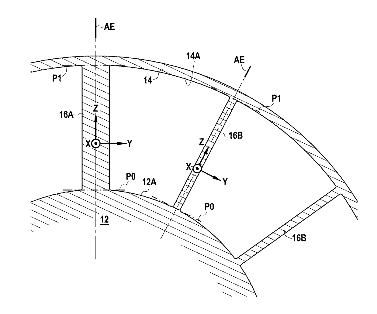
  • Optimized aerodynamic profile for an arm of a structural casing of a turbine, and structural casing having such an arm
  • Optimized aerodynamic profile for an arm of a structural casing of a turbine, and structural casing having such an arm
  • Optimized aerodynamic profile for an arm of a structural casing of a turbine, and structural casing having such an arm

Examples


Embodiment Construction

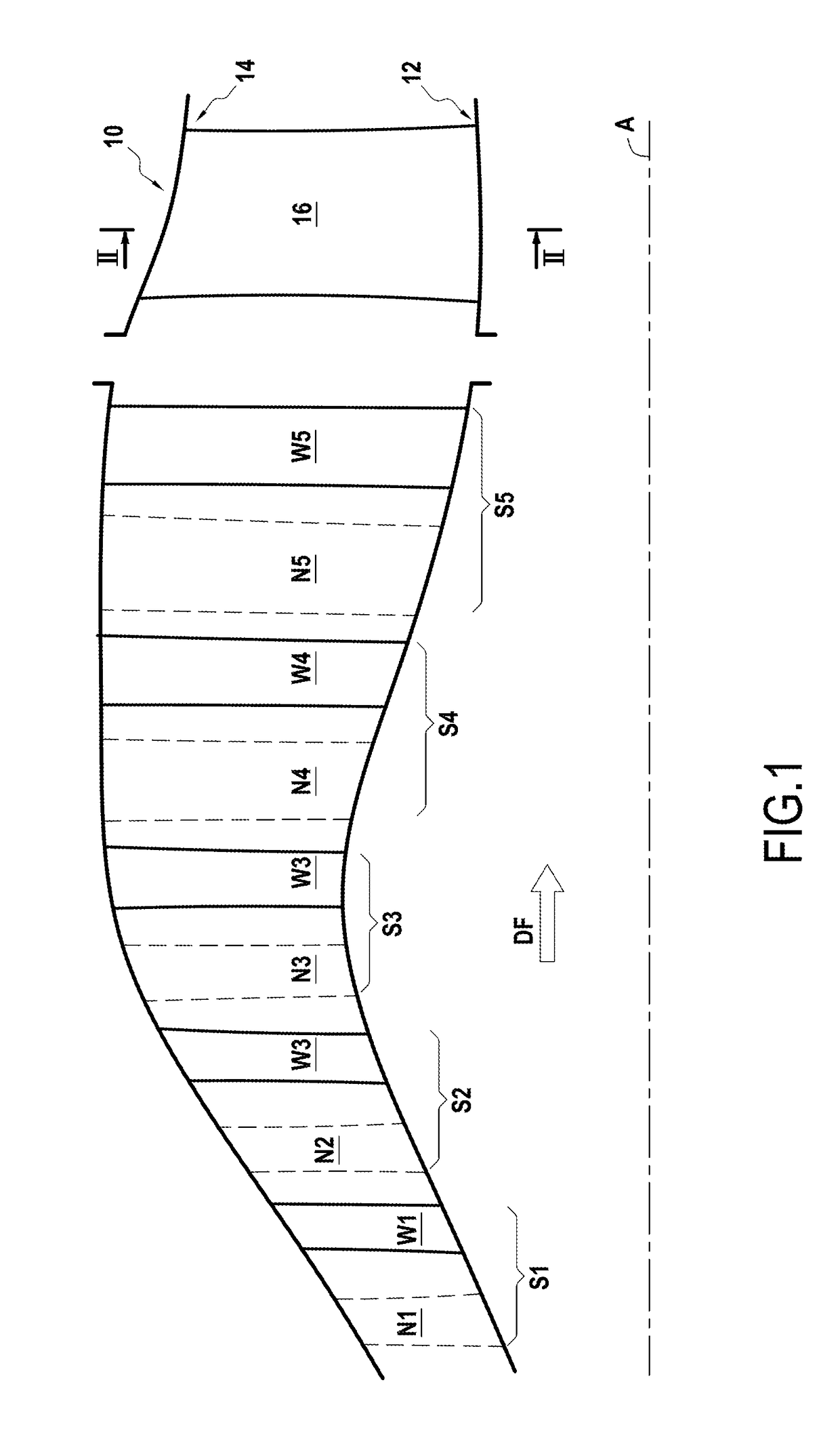
[0025]The turbine shown in axial section in FIG. 1 comprises five stages referenced respectively S1 to S5. In the direction DF going from upstream to downstream, each stage comprises a nozzle that forms a portion of the stator of the turbine and that has a plurality of radially-oriented vanes, and a rotary wheel that forms a portion of the rotor of the turbine and that likewise includes a plurality of radially-oriented blades.

[0026]In FIG. 1, the vanes of the nozzles of stages S1 to S7 are given references N1 to N5, whereas the blades of rotary wheels of stages S1 to S5 are given respective references W1 to W5.

[0027]In known manner, the vanes of the nozzles are fastened at both ends to stationary structure portions, while the blades of the rotary wheels are fastened to a rotary disk via their roots that are formed at their radially-inner ends closer to the axis of the rotation A of the turbine, the disks of the respective wheels being constrained to rotate together. In the example s...


PUM


Abstract

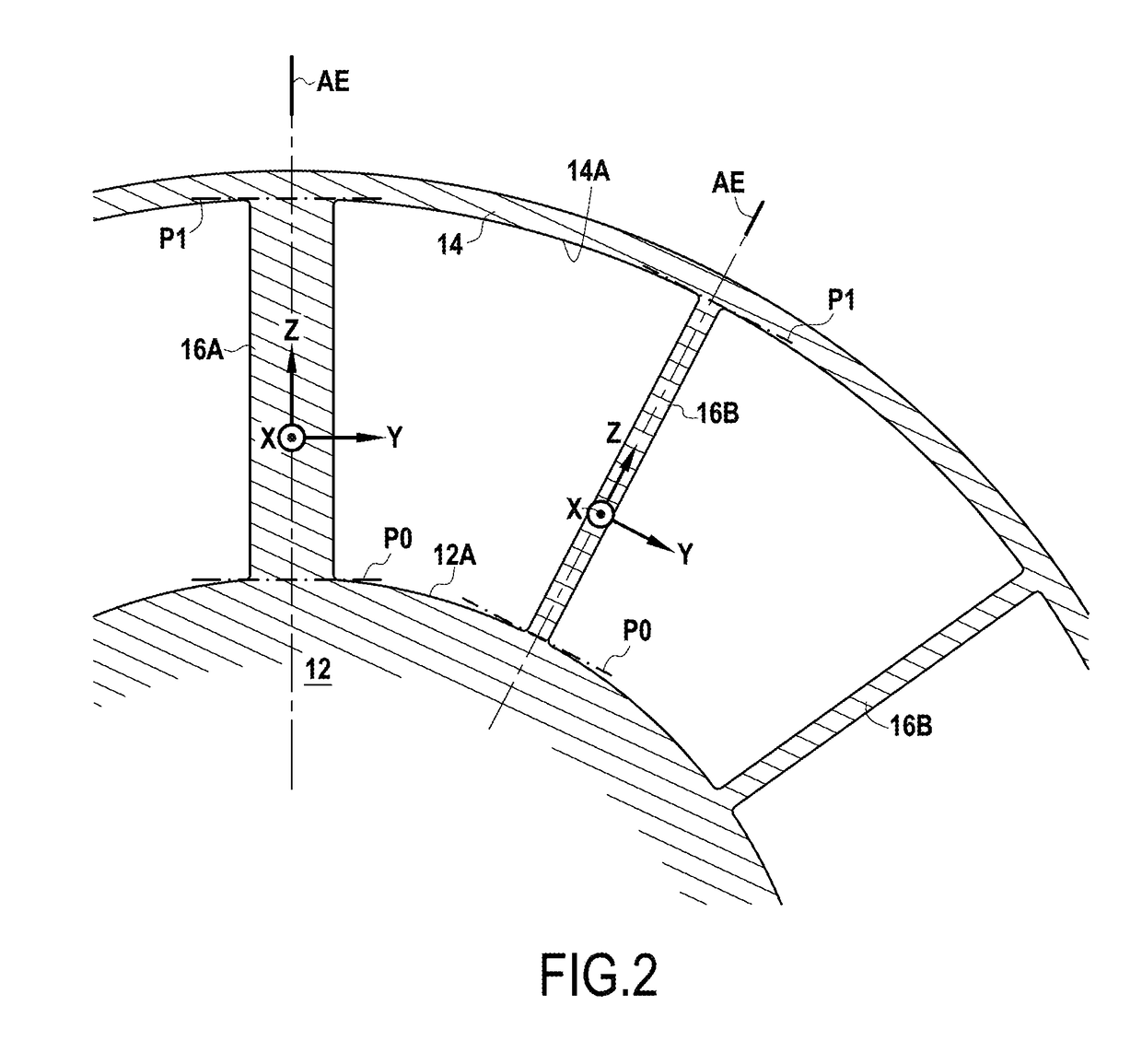
When cold and in the non-coated state, the aerodynamic profile is substantially identical to a nominal profile determined by the Cartesian coordinates X,Y, Zadim given in Table 1, in which the coordinate Zadim is the quotient D / H where D is the distance of the point under consideration from a first reference plane P0 situated at the base of the nominal profile, and H is the height of said profile measured from the first reference plane to a second reference plane P1. The measurements D and H are taken radially relative to the axis of the turbine, while the X coordinate is measured in the axial direction of the turbine.

Description

CROSS-REFERENCE TO RELATED APPLICATION[0001]This application claims the benefit of priority to U.S. Patent Application No. 62 / 504,567, filed on May 11, 2017, the entirety of which is incorporated by reference herein.INTRODUCTION[0002]The present disclosure relates to an aerodynamic profile for an arm of a structural casing of a turbine.[0003]In particular, the disclosure relates to the aerodynamic profile of an arm connecting a central hub and a shroud of such casing.[0004]The disclosure relates in particular to the aerodynamic profile of an arm belonging to a series of arms connecting the central hub and the shroud.[0005]More particularly, the turbine is a low pressure turbine of the type used in a turbojet of an aircraft.[0006]In particular, the structural casing is an exhaust casing of the turbine.[0007]The exhaust casing may be of the type disclosed in the published US patent application No. 2007068136, the contents of which is herein incorporated.[0008]An arm of a structural ca...

Claims


Application Information

Patent Timeline
Patent Type & Authority Applications(United States)
IPC IPC(8): F01D9/04
CPCF01D9/041F05D2240/128F05D2250/74F05D2220/323F01D5/141F01D25/162F01D25/30Y02T50/60
Inventor PINTAT, LUDOVICGINIBRE, PIERRELEONARDON, VINCENT NICOLASMARCHE, PIERRE HERVE FERNANDMERVANT, THOMAS MICHEL JULIEN
Owner SN DETUDE & DE CONSTR DE MOTEURS DAVIATION S N E C M A
Learn More