Penile Pump with Side Release Mechanism

Inactive Publication Date: 2009-11-19
AMS RES CORP
View PDF99 Cites 9 Cited by
  • Summary
  • Abstract
  • Description
  • Claims
  • Application Information

AI Technical Summary

Benefits of technology

[0017]Furthermore, since the patient can grasp the valve housing along the sides of the length, i.e., surfaces with larger surface area, less pressure need be applied to achieve the successful opening of the check valves. In other words, by increasing the surface area that is engaged by the patient's fingers and appropriately positioning the actuating bar, less force need be exerted by the patient to achieve the desired result.
[0018]The textured surface of the valve housing not only helps the patient identify the correct portion of the pump and valve assembly to actuate, it also serves to prevent slippage once the patient begins to compress the housing. Thus, what is achieved is an efficient and ergonomic pump and valve assembly for an implantable prosthesis. The pump and valve assembly can advantageously be formed from a minimal number of components. That is, all that need be molded are a valve block and a corresponding pump bulb which surrounds the valve block. The various check valves can be inserted into the valve block and then placed within the interior of the pump bulb, thus forming a completed assembly. This results in certain manufacturing efficiencies, thus reducing both cost and time of production.
[0019]To further improve the operational efficiency of the pump and valve assembly, the check valve is made of a metal material with a plastic member disposed over a segment of the metal material. The p

Problems solved by technology

This compression causes actuati

Method used


Image

  • Penile Pump with Side Release Mechanism
  • Penile Pump with Side Release Mechanism
  • Penile Pump with Side Release Mechanism

Examples


Example

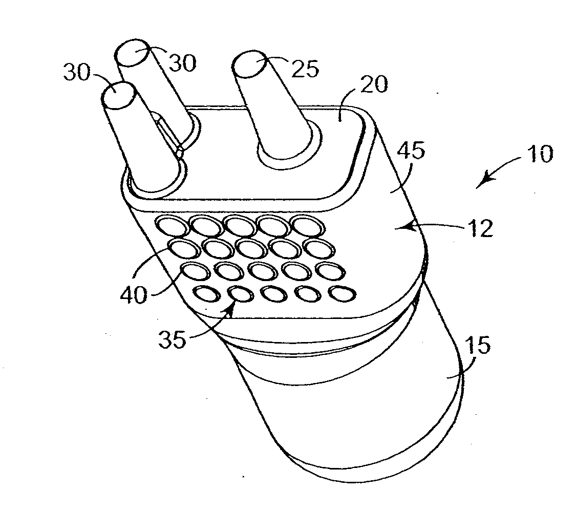
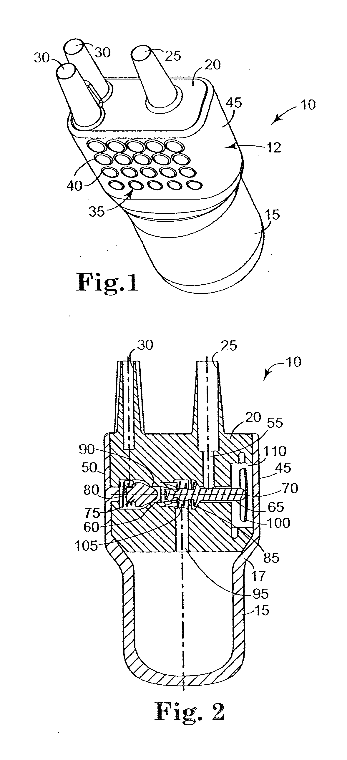
[0037]Referring to FIG. 1, a pump and valve assembly is illustrated and generally referred to as 10. Pump and valve assembly 10 includes two different sections: valve housing 12 and pump bulb 15. Pump bulb 15 is a compressible member, defining a chamber more clearly shown in FIG. 2. Valve housing 12 is fluidly coupled to pump bulb 15 and contains the various other working components of pump and valve assembly 10. Pump and valve assembly 10 will be fluidly coupled to a reservoir and a pair of cylinders (not shown). This is accomplished through tubing connected to reservoir coupling 25 and cylinder couplings 30, which are integral with valve housing 12. Pump and valve assembly 10 is configured such that pump bulb 15 extends from one end of valve housing 12, while reservoir coupling 25 and cylinder couplings 30 extend from the other. Thus, when implanted in the patient, reservoir coupling 25 and cylinder couplings 30, and the fluid tubing they are coupled to, are oriented toward the pa...


PUM


Abstract

A pump and valve assembly for an implantable prosthesis is provided with an internal actuating bar positioned such that when any portion of the housing is compressed, the check valves within are opened allowing for deflation of the cylinders. The pump and valve assembly also includes a textured surface over a portion of the housing to allow for quick identification of the component, as well as to make it easier for the patient to grasp it. The valve assembly further comprising an actuating bar which has ribs to enhance the spring force applied to a flow valve, a support structure to support and appropriately position the actuating bar, and a check valve made of metal with a segment covered with a plastic material.

Description

CROSS REFERENCE TO RELATED APPLICATIONS[0001]This application is a continuation application of Ser. No. 10 / 820,660, filed Apr. 8, 2004, which is a divisional application of Ser. No. 10 / 006,335, filed on Dec. 3, 2001 (Now U.S. Pat. No. 6,723,042), entitled “PENILE PUMP WITH SIDE RELEASE MECHANISM,” which is a continuation-in-part of related patent application Ser. No. 09 / 749,075 entitled “PENILE PUMP WITH SIDE RELEASE MECHANISM” which was filed on Dec. 27, 2000, and claims the priority of provisional application Ser. No. 60 / 295,326 entitled “PENILE PUMP IMPROVEMENTS” which was filed Jun. 1, 2001 (the entire contents of each of which are herein incorporated by reference).BACKGROUND[0002]This invention generally relates to a pump and valve assembly for inflating a prosthesis. More particularly, the invention relates to pressure-based mechanisms that inhibit spontaneous inflation of the prosthesis, including stiffening and support mechanisms that also improve the function of the valve.[...

Claims


Application Information

Patent Timeline
IPC IPC(8): A61F5/00A61F2/26
CPCA61F2/26
Inventor ALMLI, JOHN G.KUYAVA, CHARLES C.MORNINGSTAR, RANDY L.WATTS, KEVIN R.
Owner AMS RES CORP
Why Eureka
Try Eureka