[0006]Proceeding from the explained disadvantages of the known prior art, the object on which the invention is based is therefore that of designing a radial rolling bearing, in particular deep-groove rolling bearing which is formed with a bearing cage which is simple and cost-effective to produce and with which, firstly, axial guidance of the rolling bodies which are embodied as spherical disks is ensured, and secondly, friction-heat-generating contact between the spherical disks and the bearing cage can be prevented even at low bearing speeds and / or under mixed axial and radial bearing loading.DESCRIPTION OF THE INVENTION
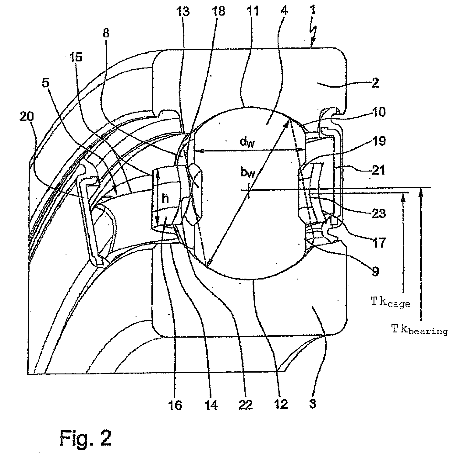
[0009]According to claim 2, it is provided in the radial rolling bearing embodied according to the invention that preferably central depressions are formed into the side surfaces of the rolling bodies, which depressions are provided as an additional
lubricant reservoir for the radial rolling bearing. Said central depressions are preferably formed in the manner of circular flat recesses, from which the
lubricant, which is filled in during the
assembly of the bearing, automatically flows out into the bearing
interior space, which is preferably sealed off by means of lateral sealing rings, under
centrifugal force during operation of the bearing. At the same time, said depressions have the
advantage that, as a result, the
mass center of gravity of the rolling bodies is moved radially outward toward their running surfaces, and the running properties of the rolling bearing are therefore significantly improved.
[0010]According to claim 3, a further feature of the radial rolling bearing designed according to the invention is that the lines of contact between the side surfaces of the rolling bodies and the longitudinal webs of the cage pockets can preferably be produced by means of axial wedge-shaped depressions which are formed longitudinally centrally into the longitudinal webs and which extend over the width of the side surfaces of the rolling bodies. During bearing operation, said wedge-shaped depressions are not in permanent contact with the side surfaces of the rolling bodies, but in the event of guidance, are in guiding contact with said side surfaces each at two points. Furthermore, it is advantageous for the resulting wedge edge on the wedge-shaped depressions to be of rounded design in order to prevent premature wear of said wedge edge.
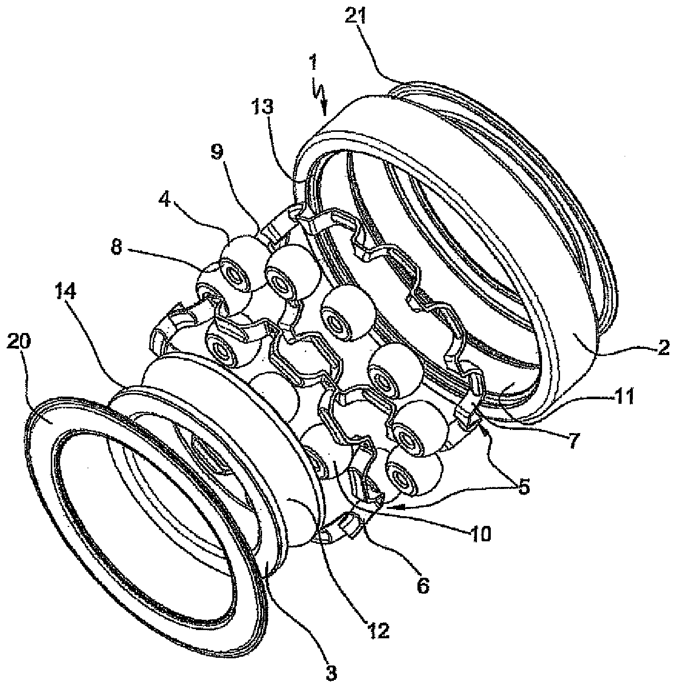
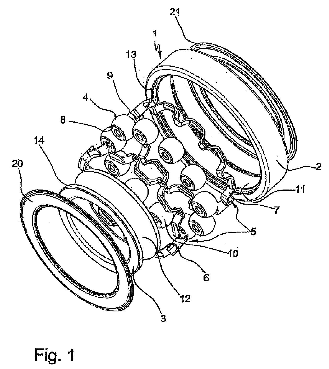
[0011]According to claims 4 and 5, the radial rolling bearing according to the invention is also characterized in that the transverse webs, which are formed so as to be domed corresponding to the radii of the running surfaces of the rolling bodies, of the cage pockets extend at both sides beyond said running surfaces in such a way that the longitudinal webs, which are connected to said transverse webs by means of rounded transition regions, of the cage pockets are arranged with a spacing to the side surfaces of the rolling bodies. The arrangement of the longitudinal webs of the cage pockets spaced apart from the side surface has the
advantage that the rolling bodies simultaneously have an axial degree of freedom, which is delimited by the upper and lower sides of the wedge-shaped depressions in the longitudinal webs, of approximately 12° to 18°, by means of which the rolling bodies can self-align to the
pressure angle of the radial bearing under radial and axial bearing loading.
[0013]The features of the radial bearing designed according to the invention as per claims 7 and 8 finally also contribute to the achievement of the object, according to which claims the bearing cage is either formed as a punched, drawn, embossed part, which can be produced without
cutting, composed of a
metal material, or as an injection-molded part composed of an
engineering plastic or high-temperature-resistant plastic or, alternatively, of a
fiber-composite plastic composed of fabric reinforcement and
resin matrix. In terms of the
metal materials, primarily steel,
brass and aluminum have been proven to be particularly suitable, with which the bearing cage can additionally be coated entirely, or limited to its contact points with the rolling bodies, with functional coatings composed of hard material,
chromite,
oxide ceramics or
molybdenum, or encapsulated with an
engineering plastic. In contrast, suitable
engineering plastics for the bearing cage are PA 66 or PA 46 with or without inclusions of glass fibers, while it is possible as high-temperature-resistant plastics to use for example PAEK, PEEK, TPI or PAI with suitable additives or inclusions of glass fibers. Said materials have proven to be particularly cost-effective in
purchasing terms and also permit the use of more cost-effective production processes for the bearing cage, such that radial bearings formed with bearing cages of said type can be produced with low overall production costs.
[0014]The radial rolling bearing designed according to the invention therefore has the
advantage over the radial rolling bearings known from the prior art that, as a result of the formation of the bearing cage with bearing pockets in which the rolling bodies are guided axially merely by means of two double lines of contact, the kinematic conditions in a radial bearing are taken into consideration in that said radial bearing has an axial guide for the rolling bodies, by means of which the tumbling movements, or tilting movements transversely with respect to the running direction, of the rolling bodies which occur below a permissible minimum speed no longer lead to friction heat and to an impermissible increase in the
operating temperature of the radial rolling bearing. At the same time, the rolling bodies have, as a result of their line-of-contact guidance in the cage pockets, a sufficient degree of freedom in the axial direction, by means of which said rolling bodies can self-align to the pressure angle of the radial rolling bearing present under radial and axial bearing loading, without coming into contact with the bearing cage. Furthermore, a bearing cage of said type has also proven to be advantageous with regard to low production costs, since said bearing cage is of structurally simple design and can be produced from cost-effective materials and using cost-effective production and
assembly processes.

